10
A. Heat Pump Unit/LAS Terminals – Connects to Heat Pump and
Leaving Air Sensor (LAS).
±: LAS terminals. The LAS monitors the heat pump coil leaving air
temperature.
W2: Auxiliary Heat. When energized (W2 made to R), turns on the
heat pump auxiliary heat.
G: Blower. When energized (G made to R), turns on the
indoor blower.
Y1: Compressor. When energized (Y1 made to R), turns on the heat
pump first stage compressor.
Y2: Compressor. When energized, (Y2 made to R), turns on the
heat pump second stage compressor.
O/B: Reversing Valve. When energized (O/B made to R), engages
the heat pump reversing valve.
R: Heat pump unit 24V power. Powers Digitract 4-2 and
thermostats.
E: Emergency Heat. Separate output (E made to R) to cycle additional
stages (if applicable) when in the emergency heat mode.
L: Compressor Fail Flag. Connected to L of STAT1 terminal. See B.
C: Heat pump unit 24V power return.
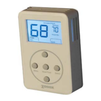
B. Thermostat Terminals – Connects up to four zone heat pump
thermostats.
L: Compressor Fail Flag. On STAT1 only. Connected to L of Heat
Pump Unit terminal (see A). If the heat pump compressor fails,
the heat pump will energize L (R made to L) which will turn on
an indicator light on thermostat 1. This feature is not available
on all heat pumps and/or thermostats.
E: Auxiliary/Emergency Heat. On STAT 1 only. Connected to E
terminal on STAT 1. When thermostat 1 is in the emergency
heat mode and making a heat call, Y is locked out and W is
energized as the first stage of heat. The W2 and E outputs from
the controller will be energized simultaneously.
NOTE: When the controller receives a STAT 1 E input from the
thermostat W terminal when in the normal heat mode, it is
ignored. The W2 output of the controller is cycled according to
leaving air temperature.
0/B: Mode control. For O thermostats, thermostat is in cool mode
when energized (O/B made to R) and in heat mode when not
energized. The reverse is true for B thermostats.
R: Heat pump unit 24V power. See A.
Y: Compressor. When energized (Y made to R), requests that the
DGHP4-2 energize the heat pump compressor.
G: Blower. When energized (G made to R), requests that the
DTHP4-2 energize the indoor blower fan.
C: Heat pump unit 24V power return.
C. Damper Terminals – Connects dampers for up to four zones and
damper power supply.
TR1/
TR2: 24V AC transformer terminals. This transformer powers only
the zone dampers.
1 1: Zone damper 1. When energized, powers zone damper 1 closed.
2 2: Zone damper 2. When energized, powers zone damper 2 closed.
3 3: Zone damper 3. When energized, powers zone damper 3 closed.
4 4: Zone damper 4. When energized, powers zone damper 4 closed.
D. Damper Status Lights – Light on when corresponding zone
damper is closed.
E. Reversing Valve Selection Jumper – Configures Digitract 4-2 to
energize reversing valve in cool mode or heat mode. Place on O and
center pin to energize reversing valve in cool mode. Place on B and
center pin to energize in heat mode.
F. Board Number – This number indicates the circuit board number
and revision. May need to know this number if conferring with
technical support.
G. Microcontroller – Responsible for activation and control of the
unit and dampers based upon thermostat input. Occasionally
software upgrades may become available. If so, the Digitract 4-2
software can be field upgraded by changing this microcontroller.
H. Power Switch – When OFF, power from the heat pump transformer
is disconnected from the Digitract 4-2 and thermostats. When ON, power
from the heat pump transformer is supplied to the Digitract 4-2 and
the zone thermostats.
I. Heat Pump Status LEDs – Indicates what the DTHP4-2 is
energizing on the heat pump.
O/B: Reversing valve, yellow. On when the reversing valve is
energized.
Y1: Compressor, yellow. On when the first stage compressor is
energized.
Y2: Compressor, yellow. On when the second stage compressor is
energized.
G: Blower, green. On when the indoor blower is energized.
W2: Auxiliary heat, red. On when the auxiliary heat is energized.
PWR: Power, orange. On when power at R and C and the Power
Switch is on. Flashing when in Capacity Control cut out mode.
See Status Lights section, page 9, for further information.
J. Leaving Air Sensor Potentiometer – Turn to calibrate the leaving
air sensor, if required. See Calibration, in Capacity Controller section.
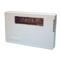
SYSTEM CONTROLLER – HEAT PUMP DTHP4-2
COMPONENTS (Continued)