23
DAMPER TRANSFORMER
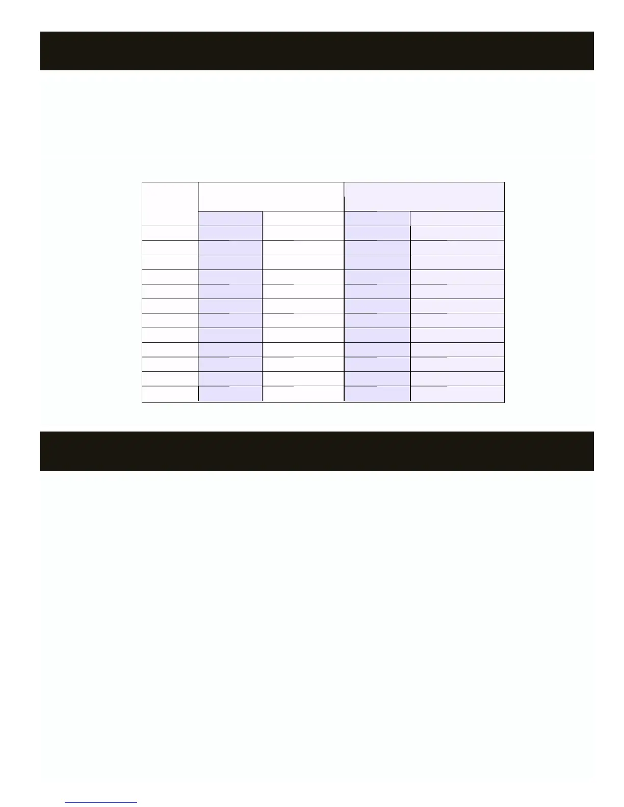
TRANSFORMER/FUSE SIZING
NUMBER TR SERIES TR SERIES TR SERIES TR SERIES MED. PRESSURE/HEAVY DUTYMED. PRESSURE/HEAVY DUTYMED. PRESSURE/HEAVY DUTYMED. PRESSURE/HEAVY DUTY
OF (SPRING OPEN) DAMPERS (SPRING OPEN) DAMPERS (SPRING OPEN) DAMPERS (SPRING OPEN) DAMPERS (POWER OPEN) DAMPERS (POWER OPEN) DAMPERS (POWER OPEN) DAMPERS (POWER OPEN) DAMPERS
DAMPERS XFMR PWR XFMR PWR FUSE SIZE FUSE SIZE
1 12 VA 1 AMP 6 VA 1 AMP
2 24 VA 2 AMP 12 VA 1 AMP
3 36 VA 2 AMP 18 VA 1 AMP
4 48 VA 3 AMP 24 VA 2 AMP
5 60 VA 3 AMP 30 VA 2 AMP
6 72 VA 4 AMP 36 VA 2 AMP
7 84 VA 5 AMP 42 VA 3 AMP
8 96 VA 5 AMP 48 VA 3 AMP
9 108 VA 6 AMP 54 VA 3 AMP
10 120 VA 6 AMP 60 VA 3 AMP
11 132 VA 7 AMP 66 VA 4 AMP
12 144 VA 7 AMP 72 VA 4 AMP
XFMR PWR
FUSE SIZE
Notice:
All wiring must meet state and local codes.
The 24V transformer connected to TR1 and TR2 of the Digitract 4-2
System Controller powers the zone dampers. The power rating of the
transformer must be sufficient to power the number of dampers used.
Also, a properly rated in line fuse must be used on the secondary of
the transformer. To determine the power rating of the transformer and
the amperage rating of the fuse, use the table below. If using a
combination of spring open and power open dampers, size as if all
dampers are spring open.
Note: The System Controller and thermostats are powered by the
HVAC unit transformer via terminals R and C.
STARTUP TEST, GAS/ELECTRIC DTGE4-2
1. If no heating system, go to step 12.
2. At System Controller:
a. Disconnect LAS sensor at + - terminals and place jumper wire
between + - terminals.
b. Turn power switch ON.
3. Turn off all thermostats except zone 1.
4. At zone 1 thermostat:
a. Set power switch on.
b. Set to Heat mode.
c. Set Fan switch to Auto mode.
d. Set heat setpoint several degrees above room temperature.
5. At System Controller:
a. Verify W and PWR lights are on. If not, cycle System Controller
power switch OFF and then ON and recheck.
b. If jumper JU1 is on B, verify G light is on.
c. Verify DPR 1 light is off and DPR 2 through DPR 4 lights are on.
6. At HVAC unit, verify furnace is on and blower fan is running. If the
G light on System Controller is not on, the blower fan is controlled
by the furnace and there will be a delay before it turns on.
7. At zone 1, verify air is coming out of the register/diffuser.
8. At next zone:
a. Verify air is not coming out of register/diffuser.
b. At thermostat:
b-1 Set power switch on.
b-2 Set to Heat mode.
b-3 Set Fan switch to Auto mode.
b-4 Set heat setpoint several degrees above room
temperature.
c. Verify air is now coming out the register/diffuser.
9. At previous zone, turn thermostat off and verify air stops coming out
of the register/diffuser.
10. Repeat steps 8 and 9 for all remaining zones.
11. If no cooling system, reconnect LAS to the + - terminals of the
System Controller and test is complete.
12. Disconnect all wires from the + - terminals of the System Controller.
13. Turn off all thermostats except zone 1.
14. At zone 1 thermostat:
a. Set power switch on.
b. Set to Cool mode.
c. Set Fan switch to Auto mode.
d. Set cool setpoint several degrees below room temperature.