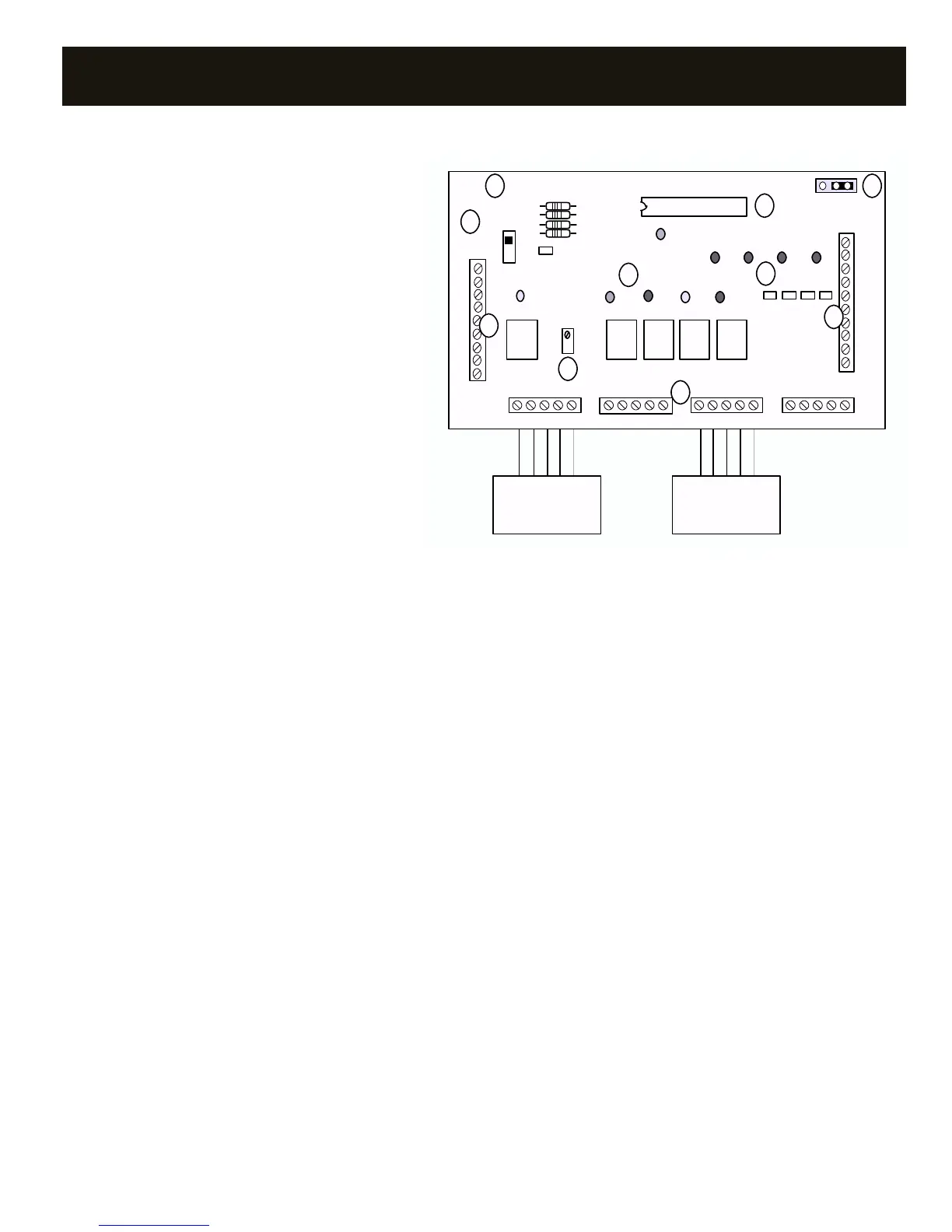
A. HVAC Unit/LAS Terminals – Connects to HVAC unit and
Leaving Air Sensor (LAS).
±: LAS terminals. The LAS monitors the leaving air
temperature.
W1: First stage heat. When energized (W1 made to R),
energizes first-stage heat.
W2: Second stage heat. When energized (W2 made to R),
energizes second-stage heat.
G: Blower. When energized (G made to R),
energizes the indoor blower.
Y1: First stage cool. When energized (Y1 made to R),
energizes first stage cooling.
Y2: Second stage cool. When energized (Y2 made to R),
energizes second stage cooling.
R: HVAC unit 24V power. Powers the DigiTract 4-2 board
and zone thermostats.
C: HVAC unit 24V power return.
B. Thermostat Terminals – Connects up to four zone
thermostats.
W: Heat call. When energized (W made to R),
requests the Digitract 4-2 to run in heat mode.
R: HVAC unit 24V power.
Y: Cool call. When energized (Y made to R),
requests the Digitract 4-2 to run in cool mode.
G: Blower Fan- When energized (G made to R), requests the
DigiTract 4 to turn on the indoor blower fan.
C: HVAC unit 24V power return.
C. Damper Terminals – Connects dampers for up to four zones and
damper power supply.
TR1/
TR2: 24V AC transformer terminals. This transformer powers only
the zone dampers.
1 1: Zone damper 1.
When energized, powers zone damper 1 closed.
2 2: Zone damper 2.
When energized, powers zone damper 2 closed.
3 3: Zone damper 3.
When energized, powers zone damper 3 closed.
4 4: Zone damper 4.
When energized, powers zone damper 4 closed.
D. Damper Status LEDs – On when corresponding zone damper is
being powered closed.
E. Board Number – This number indicates the circuit board number
and revision. May need to know this number if conferring with
technical support.
F. Heat Mode Fan Control Selection Jumper – In the A position,
the blower is energized by the furnace when heat is energized
(gas furnaces). In the B position, the blower is energized by the
DTGE4-2 when heat is energized (electric furnaces).
G. Microcontroller – Responsible for activation and control of the
unit based upon thermostat input. Occasionally software upgrades
may become available. If so, the Digitract 4-2 software can be field
upgraded by changing this microcontroller.
H. HVAC System Status LEDs – Indicates what the DTGE4-2 is
energizing on the HVAC system.
Y1: Compressor, yellow. On when the first-stage cool is energized.
Y2: Compressor, yellow. On when the second-stage cool is energized.
G: Blower, green. On when the indoor blower is energized.
W1: Heat, red. On when first stage heat is energized.
W2: Heat, red. On when second stage heat is energized.
PWR: Power, orange. On when power at R and C and the Power
Switch is on. Flashing when in Capacity Control cut out mode.
See Status Lights section, page 6, for further information.
I. Leaving Air Sensor Potentiometer – Turn to calibrate the
leaving air sensor if required. See Calibration in Capacity Controller
section.
J. Power Switch – When OFF, power from the HVAC unit transformer is
disconnected from the Digitract 4-2 and thermostats. When ON, power
from the HVAC unit transformer is supplied to the Digitract 4-2 and
the zone thermostats.
7
SYSTEM CONTROLLER – GAS/ELECTRIC DTGE4-2
Y1 G W1
PWR
DPR1 DPR2 DPR3 DPR4
ON
-
R
C
Y1
+
1
2
3
3
4
4
TR1
TR2
2
1
DIGITRACT 4-2 GE TWO STAGE 220108
AB
JPR1
Vx.x
R72
Y2
R8
R10
R9
R5
W2
G
W1
Y2
ZONE 1
THERMOSTAT
ZONE 3
THERMOSTAT
STAT 1
W R Y G C
STAT 2
W R Y G C
STAT 3
W R Y G C
STAT 4
W R Y G C
W R Y G CW R Y G C
W2
A
B
C
D
E F
G
H
I
J
COMPONENTS