The barometric bypass damper is for systems 5 tons or under. It utilizes
a weighted damper blade to maintain constant duct pressure. This
allows for easy installation without the need for electrical power or
wiring. The round barometric damper can be installed in any position. It
is an efficient solution for small system fan capacity control.
SIZING: When only the smallest zone is calling, the maximum
amount of excess supply air will flow through the bypass damper. To
determine the proper size bypass damper to use, do the following steps:
Step 1: Calculate bypass air volume as follows.
A) Calculate total air volume at 400 CFM
per ton.
B) Calculate air volume of smallest zone in
CFM.
C) Calculate bypass air volume by subtract-
ing the smallest zone air volume from the
total.
(A - B = C)
Step 2: Select damper from sizing table.
Once you have calculated the bypass air volume from Step 1, use the
BAROMETRIC BYPASS SELECTION TABLE. From the table, select the
bypass damper with the CFM rating equal to or greater than the value
calculated in Step 1. For rectangular barometric dampers, use a
ductulator to convert from round to rectangular.
If bypassing more than 2000 CFM, use electronic bypass damper.
Example: You have a 4 ton system. Your smallest zone will use 500
CFM. The total CFM is 1600 CFM (400 * 4). Your bypass CFM is 1100
(1600 - 500). From the table, you determine that a 12” bypass damper
is needed.
Do not use the barometric bypass in any system over 5 tons.
For systems over 5 tons, or to bypass more than 2000 CFM, use the
electronic bypass.
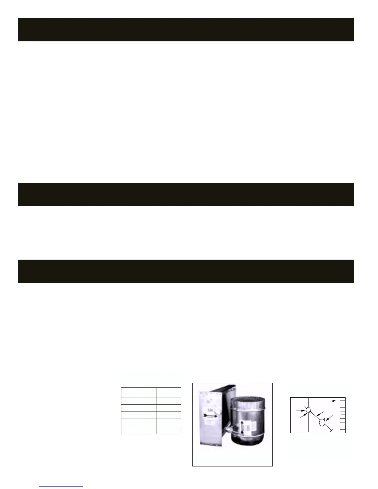
Bypass dampers are used to provide constant air delivery through the air
handling unit. This is done by bypassing excess air from the supply duct
back to the return duct. As a zone is satisfied, its zone damper closes.
When this happens, the bypass damper opens just enough to bypass the
excess air. This will control static pressure and noise at the diffusers.
Zonex Systems offers two types of bypass dampers, Barometric and
Electronic. Each is available in round or rectangular configuration.
Barometric bypass dampers are limited to systems of 5 tons. Electronic
dampers can be used on any size system. For systems 5 tons or smaller,
the barometric bypass can be used. For systems over 5 tons, we
recommend the electronic bypass.
RECTANGULAR & ROUND
BAROMETRIC BYPASS
BYPASS DAMPERS
BYPASS DAMPERS – BAROMETRIC
AIRFLOW
1
2
4
3
1. Damper Shaft
2. Lock Nut
3. Lever Arm
4. Counter Weight
BAROMETRIC BYPASS
DAMPER
Diameter CFM
9” 650
10” 800
12” 1200
14” 1600
16” 2000
BAROMETRIC BYPASS
SELECTION TABLE
18
ZONE DAMPERS
SIZING ZONE DAMPERS
If the ductwork already exists, simply size the damper to fit the ductwork.
For new systems or retrofit jobs:
a) Determine CFM from heat gain or loss calculations.
b) Select damper size by using a duct sizing table or calculator.
c) Select a Zonex Systems damper to fit the duct size selected for
that zone.
DAMPER INSTALLATION NOTES
1. Do not exceed 700 FPM in a register/diffuser branch duct.
2. If a damper is installed within 3 feet of register/diffuser, install sound
attenuating flex duct between damper and outlet.
3. Zone dampers should be preceded by 2’-4’ of straight pipe where
possible.
4. In attic installations and high humidity areas, the Zonex Systems
damper should be insulated along with the ductwork. The hat section
on the damper is delivered with insulation between the hat section
and pipe. Therefore, insulation should be applied to the round pipe
and be butted against the hat section, (do not insulate the motor or
relay board). Both motor and the relay board generate enough heat
so no condensation will develop on the hat section.
5. Remember to allow a 16” gap in the duct for Heavy Duty rectangular
dampers.
6. Low and medium pressure rectangular dampers slide into a 3” wide
cutout in the ductwork.
7. Install TR round dampers to the motor in the 9 to 3 o’clock position.
Do not install damper so the motor is in the 4 to 8 o’clock position.