The HVAC system is sized to handle the load of the entire home
or building. Because of this, when all the zones are not calling, the load
to the HVAC system can diminish below its designed capacity. Left
unchecked, the HVAC unit could freeze up or overheat. To compensate
for this, the Digitract 4-2 is furnished with a built in Capacity Controller.
The basic function of the Capacity Controller is to monitor the leaving air
temperature and cycle the unit off when the air is out of operating range
and, after a minimum four minute time delay, turn the unit back on when
the air temperature has returned within operating range. Additionally, for
heat pumps the Capacity Controller will turn on the heat pump auxiliary
heat if the coil leaving air temperature is not hot enough in heat mode.
W1 Heat Operation – Upon a heat call, the controller will energize W1
if the leaving air temperature is less than 145°F. W1 will deenergize if
the LAT exceeds 145°F. The W1 LED will then cycle off and the PWR LED
will begin to flash indicating a capacity control cutout. After a 4-minute
recycle timer has completed, W1 will energize if the LAT is below 145°F.
W2 Heat Operations – After W1 has operated continuously for 4
minutes and the LAT is 120°F or less, W2 will energize. W2 will remain
energized until the LAT rises above 135°F or if all heat calls become
satisfied. The W2 LED will then cycle off.
Y1 Heat Operation – Upon a heat call, the controller will energize Y1
and operate with a minimum run time of 4 minutes, regardless of the leaving
air temperature. At the completion of the minimum run time, if the
leaving air temperature rises above 120°F, Y1 is deenergized; the Y LED is
off and the PWR LED will flash. G will remain energized, upon which the
leaving air temperature is rechecked after 4 minutes. If the leaving air
temperature has recovered to 120°F. or lower Y1 will recycle and the
PWR LED will stop flashing. If the reversing valve jumper is in the
O position, the O/B output will be energized simultaneously with Y,
indicated by the O/B LED.
Y2 Heat Operation – After 4 minutes of continuous Y1 run time, the
leaving air temperature, LAT is checked. If the LAT is below 95°F., Y2 will
be energized and the Y2 LED will illuminate. Y2 will cycle off when the
LAT rises above 105°F., or when all heat calls are satisfied.
Auxiliary Heat – After 8 minutes of continuous Y1 operation the leaving
air temperature, LAT is checked. If the LAT is below 88°F., W2 will be
energized and the W2 LED will illuminate. W2 will cycle off when the LAT
rises above 97°F., or when all heat calls are satisfied.
Y1 Cool Operation – Upon a cool call, the controller will energize Y1
and operate with a minimum run time of 4 minutes, regardless of the
leaving air temperature. At the completion of the minimum run time, if
the leaving air temperature drops below 45°F., Y is deenergized; the Y
LED is off and the PWR LED will flash. G will remain energized, upon
which the leaving air temperature is rechecked after 4 minutes. If
the leaving air temperature has recovered to 45°F. or greater, Y will be
reenergized and the PWR LED will stop flashing. If the reversing
valve jumper is in the O position, the O/B output will be energized
simultaneously with Y, indicated by the O/B LED.
Y2 Cool Operation – After 8 minutes of continuous Y1 run time, the
leaving air temperature, LAT is checked. If the LAT is above 60°F., Y2 will
be energized and the Y2 LED will illuminate. Y2 will cycle off when the
LAT drops below 50°F., or when all cool calls are satisfied.
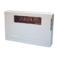
The Capacity Controller comes factory calibrated. However, if field calibration is ever necessary, perform the following:
1. Use a digital, DC voltmeter with 3 digits to the right of the decimal accuracy.
2. On the System Controller, place - probe of voltmeter to C terminal and + probe to left side of sec-
ond resistor from top (R10) as shown in adjacent diagram.
3. Measured voltage should read 2.718 VDC. If the voltage is incorrect, slowly adjust poten-
tiometer R72 until 2.718 VDC is obtained.
4. The LAS is now calibrated.
C
R72
DC
Voltmeter
2.718
+
–
STAGING AND CAPACITY CONTROL
COOLING OPERATION – DTGE4-2 AND DTHP4-2
HEAT OPERATION – GAS/ELECTRIC DTGE4-2
HEAT OPERATION – HEAT PUMP DTHP4-2
CAPACITY CONTROLLER – CALIBRATION
CAPACITY CONTROLLER – LAS INSTALLATION
11
SHIELD
A. Cut or drill a hole in selected location large enough to fit sensor through.
B. Select location to install the LAS. For gas/electric HVAC systems, sensor must be in leaving air duct, preferably as
far from the coil/heat exchanger as possible but not past the bypass tap. For heat pumps, locate LAS downstream
from indoor coil but before auxiliary heat strips.
C. Place sensor through hole made in duct and mount Capacity Controller to duct with screws. Use grommet or tape
to protect sensor wire from sharp edges.
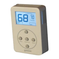
D. The cable between the LAS sensor and the controller must be installed separately from all 24 volt control and
power wiring. Using the shielded cable provided, connect the LAS between the + and – terminals of the controller
as shown. The shielded conductor is provided for installations with spark ignition or distances from controller to
LAS beyond 10’. 18/2 thermostat wire may be used in most applications.
Terminate the shield at the controller end only on the “C” terminal of the equipment terminal block.
Important: The shield at the LAS end of the wire must not be grounded, or attached to any other terminal.
The shield should be cut and taped off at the LAS end to prevent grounding.