Do you have a question about the Zte ZXR10 3928A and is the answer not in the manual?
Provides safety instructions and guidelines for operating the equipment safely.
Explains special attention items and symbols for ZXR10 3900A/3200A configuration.
Details the ZXR10 3900A/3200A series products, their applications, and general features.
Lists the various functions supported by ZXR10 3900A/3200A series products.
Presents detailed technical specifications and parameters for different models in the ZXR10 3900A/3200A series.
Explains the core operational principles of the ZXR10 3900A/3200A series Ethernet switches.
Details the physical chassis, interfaces, and back plane of the ZXR10 3228A model.
Describes the hardware structure, front and back planes of the ZXR10 3228A-EI model.
Details the hardware layout, front and back planes of the ZXR10 3228A-FI model.
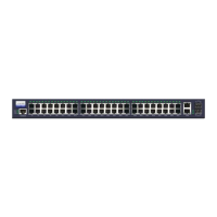
Details the chassis height, front panel, and back plane of the ZXR10 3252A model.
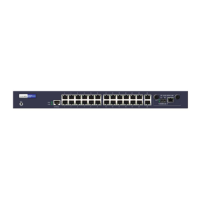
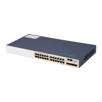
Explains the hardware structure, front panel, and back plane of the ZXR10 3928A model.
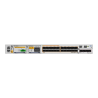
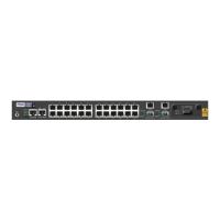
Details the hardware structure, front and back planes of the ZXR10 3928A-FI model.
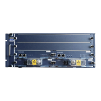
Covers the hardware layout, front panel, and back plane of the ZXR10 3952A model.
Describes the hardware configuration, front and back planes of the ZXR10 3928A-PS model.
Details the core control and switching board, its interfaces (Console, Management, Ethernet).
Provides an overview of line interface cards for ZXR10 3900A/3200A series.
Describes the FGEI sub card, its Gigabit Ethernet uplink interfaces, and indicators.
Details the FGFI sub card, its Gigabit Ethernet uplink optical interfaces, and indicators.
Covers the FGFE sub card, its Gigabit Ethernet uplink optical and electrical interfaces, and indicators.
Explains the FBFE sub card, its 100Mbps Ethernet uplink optical interfaces, and indicators.
Provides a general overview of the power modules for ZXR10 3900A/3200A series products.
Details the built-in active power supply, its input interfaces (DC and AC).
Covers the 12V standby DC power supply input for specific models.
Describes the RJ45 interfaces on ZXR10 3228A-EI for backbone node input and output.
Details the swappable 550W power supply for the ZXR10 3928A-PS model.
Covers general equipment installation, including desktop and cabinet mounting.
Instructions for installing the device on a desk, including using bottom blocks for heat dissipation.
Steps for installing the device in a 19-inch cabinet using flanges and brackets.
Details on installing AC and DC power cables for the devices.
Details on connecting the serial console cable for configuration and maintenance.
Instructions for installing network cables, including straight-through and crossover types.
Information on installing optical fiber interfaces, types, and connectors.
Steps for checking environmental conditions and powering on the equipment.
Introduces the ZXR10 RPS180 as a redundant power supply enhancement.
Details the input capabilities (AC/DC) and output voltages of the ZXR10 RPS180.
Lists the technical specifications and parameters for the ZXR10 RPS180.
Explains the working principles of the ZXR10 RPS180, including its AC and DC models.
Describes the physical chassis, card structure, and power supply types of the ZXR10 RPS180.
Details the power conversion board, CAPU, CDPU, and LPDB boards of the RPS180.
Covers equipment installation for the RPS180, including desktop and cabinet mounting.
Guidance on connecting power and console cables for the ZXR10 RPS180.
Steps for checking environmental conditions and powering on the ZXR10 RPS180.
| Model | ZXR10 3928A |
|---|---|
| Category | Switch |
| MAC Address Table | 16K |
| Jumbo Frame | 9K |
| Operating Temperature | 0°C to 45°C |
| Storage Temperature | -40°C to 70°C |
| Power Supply | AC 100-240V, 50/60Hz |
| VLAN | 4K VLAN |
| Storage Humidity | 5% to 95% (non-condensing) |
| Operating Humidity | 10% to 90% non-condensing |