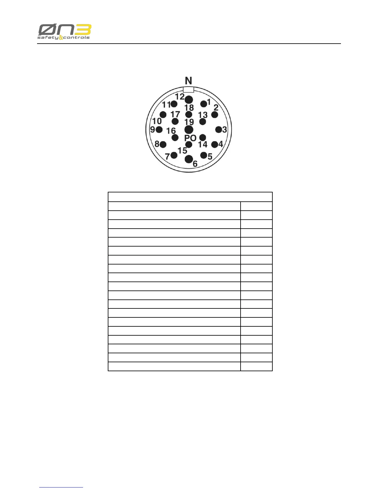
2.5.3.2 Circular connector
Signal Pin
Emergency Stop Button C1a (normally closed) 1
Emergency Stop Button C2a (normally closed) 2
Enabling Device C2o contact (normally open) 3
Enabling Device C1o contact (normally open) 4
Enabling Device C1 contact (normally open) 5
State Selector (common) 6
State Selector (bit 0) 7
State Selector (bit 1) 8
Ethernet TX- 9
Ethernet TX+ 10
Ethernet RX+ 11
Power Supply 0V dc (GND) 12
Emergency Stop Button C2b (normally closed) 13
Enabling Device C2 contact (normally open) 14
State Selector (bit 3) 15
State Selector (bit 2) 16
Ethernet RX- 17
Emergency Stop Button C1b (normally closed) 18
Power Supply +24V dc 19
Figure 18: H3 Circular connector pin-out
 Loading...