DB-25 termination to cable splitter
User must connect H3 DB-25 male connector to J2 female connector.
Circular connector to connection box
User must connect H3 circular male plug to female connector on connection box
2.6.2 Cabling: Cable Splitter or Connection Box to CN/PLC
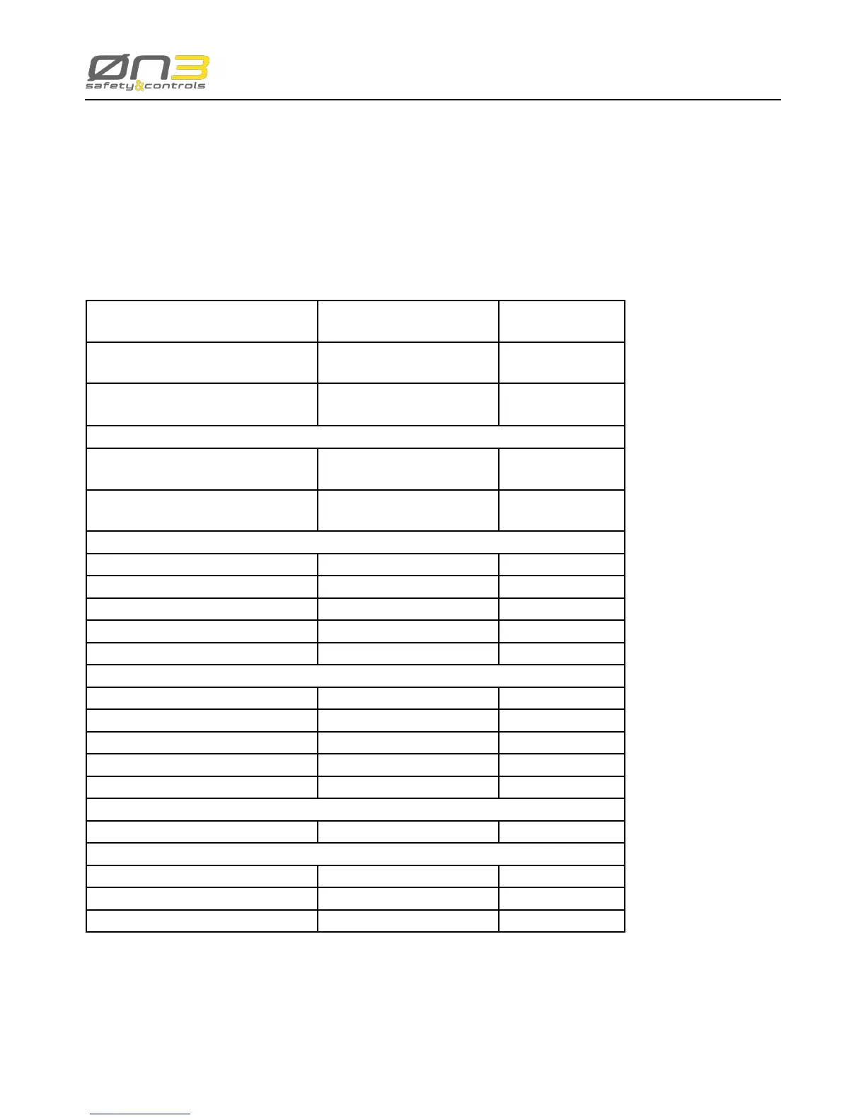
For a correct cabling please refer to the following table:
Cable Splitter ouput contact
Enabling Device
Signal meaning Note
Terminal J8 - C1
Terminal J8 - C1o
Contact C1 N.O. Contact
Terminal J8 - C2
Terminal J8 - C2o
Contact C2 N.O. Contact
Emergency Stop Push-button
Terminal J9 - C1a
Terminal J9 - C1b
Contact C1 N.C. Contact
Terminal J9 - C2a
Terminal J9 - C2b
Contact C2 N.C. Contact
State Selector
Terminal J4 - COM Common Contact
Terminal J4 - 0 Bit 0
Terminal J4 - 1 Bit 1
Terminal J4 - 2 Bit 2
Terminal J4 - 3 Bit 3
RS-422 Interface (H3 RS-422 version only)
Terminal J5 - TX+ Serial Port TX +
Terminal J5 - TX- Serial Port TX -
Terminal J5 - RX+ Serial Port RX +
Terminal J5 - RX- Serial Port RX -
Terminal J5 - GND Serial Port GND
ETHERNET interface (H3 ETHERNET version only)
RJ45 connector J12 Ethernet Port
Power Supply
Terminal J3 - 24V Power Supply 24V
Terminal J3 - GND Power Supply GND
Terminal J3 - Earth Machine Earth Ground
For a correct cabling to the connection box please refer to the indication on the connection box label
 Loading...