1.
2.
3.
VoIP Board
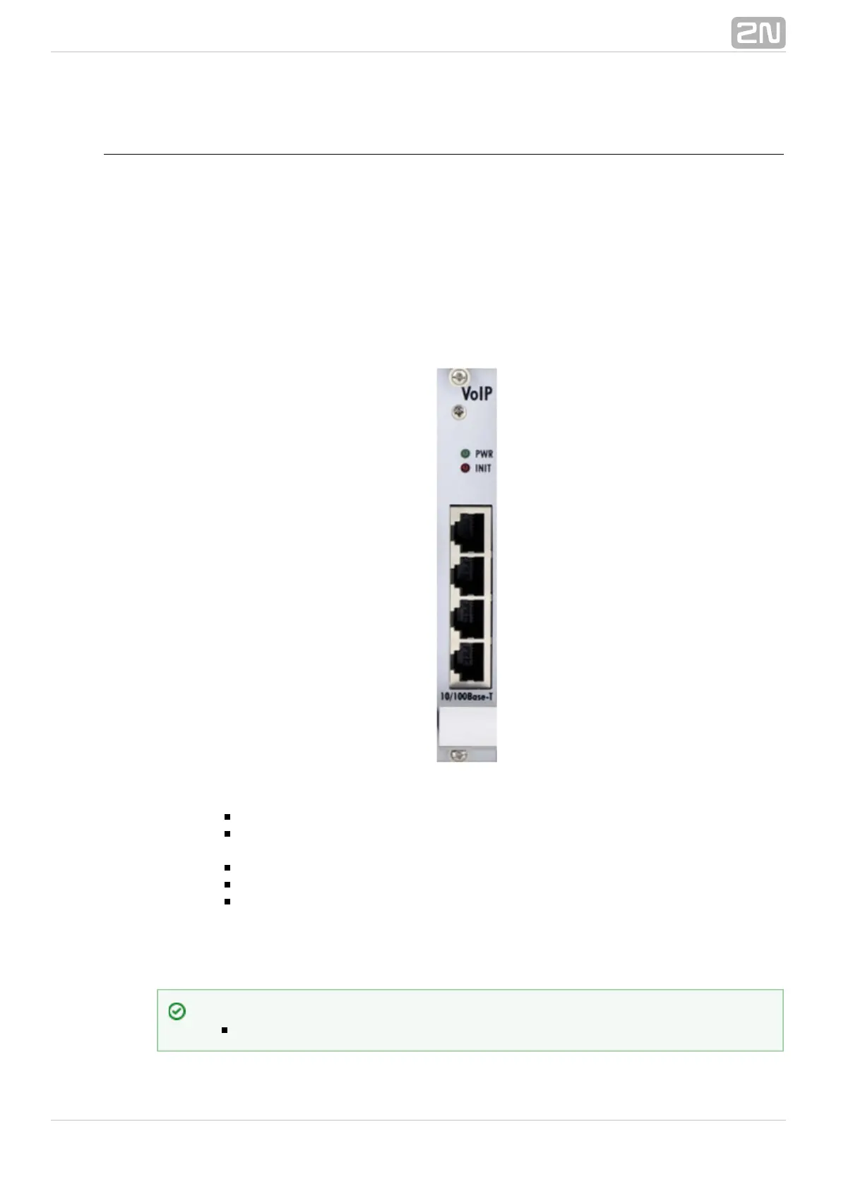
Board Description
The VoIP board contains a digital signalling processor (DSP), 4x10/100BaseT Ethernet
switch and a small carrier board with the licence chip. The main board is designed on a
6-layer PCB of the size of 160x100mm. Two board status LED indicators are located on
the front panel. Configuration (e.g. used voice codecs, IP setting) is completely
managed by the main CPU and made via a standard web interface. There is no fixed
memory (EEPROM) for the VoIP card firmware. The firmware is saved on the basic CPU
and uploaded to the VoIP card upon every VoIP card start/restart.
PWR – board supply indication
Shining: Switched on
Flashing: Board in the sleep mode
INIT – board initialisation indication
Shining for two minutes: Firmware uploading and configuration in progress
Continuous shining: Board initialisation failure
Light off: Board initialised successfully
Four RJ45 connectors of the internal 10/100BaseT Ethernet switch
The VoIP board is designed as a media gateway. It works only with media packets
(RTP); signalling packets (SIP) must be routed to the basic CPU IP address.
Tip
You have to restart the VoIP card upon any VoIP configuration change.