19
Table 1 – Inspection and Maintenance Log
Serial Number(s): Date Purchased:
Model Number: Date of First Use:
Inspection Date: Inspected By:
Component: Inspection: (See Section 2.2 for Inspection Frequency) User Competent
Person
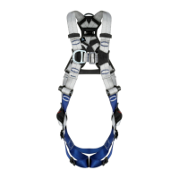
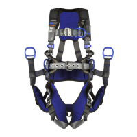
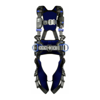
Harness Hardware
(Diagram 1)
Inspect harness hardware including buckles (1), adjusters (2), D-rings (3), Easy-Link (4),
loop keepers (5), lanyard parking (6), etc. These items must not be damaged, broken, or
distorted, and must be free of sharp edges, burrs, cracks, worn parts, or corrosion. PVC
coated hardware must be free of cuts, rips, tears, holes, etc., in the coating to ensure
non-conductivity. Ensure buckles and adjusters work smoothly.
If present, inspect the quick connect buckles by ensuring that the release tabs work freely
and that a click is heard when the buckle engages. Inspect parachute buckle spring.
Some harnesses are equipped with a “stand up D-ring” in the dorsal (back) D-ring
location. If the spring in the D-ring is damaged or lost and the D-ring no longer stands up,
this does not compromise the harness integrity. As long as the D-ring passes inspection
criteria in Step 1, it is safe to use.
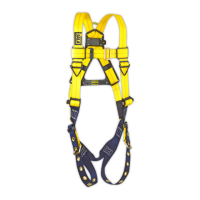
Webbing & Stitching
(Diagram 2)
Inspect webbing; material must be free of frayed, cut, or broken bers. Check for tears,
abrasions, mold, burns, or discoloration. Inspect stitching; check for pulled or cut stitches.
Broken stitches may be an indication that the harness has been impact loaded and must
be removed from service. On Delta Vest™ harnesses, inspection should include the
webbing inside the vest.
Stitched Impact Indicators
(Diagram 3)
The Stitched Impact Indicators are sections of webbing lapped back on themselves and
secured with a specic stitch pattern. The stitch pattern is designed to release when
the harness arrests a fall or is exposed to equivalent force. If an Impact Indicator
has been activated (indicated), the harness must be removed from service and
destroyed.
Labels All labels should be present and fully legible. See Figure 18.
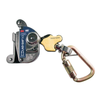
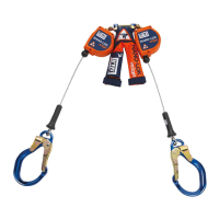
System & Subsystem
Components
Inspect each system component or subsystem according to the manufacturer’s
instructions.
Diagram 1 – Hardware
1
1
11
1 1
2
2
3
4
6
6
5
5
5
Diagram 2 – Webbing
Cut
Frayed
Heavily
Soiled
Welding
Burns
Diagram 3 – Impact
Indicator
ü Good
û Indicated
 Loading...