Installation Instructions G5 - Revision C, September 2019
11
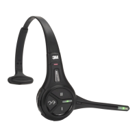
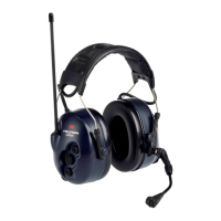
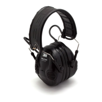
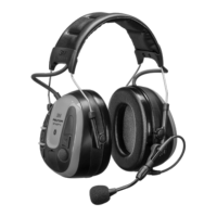
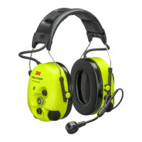
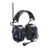
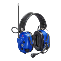
3M™ Drive-Thru System Model G5
Installation Instructions G5
Revision C, September 2019
• When charging is complete, the batteries are ready for use.
Figure 6.
Power plugs are available on both sides of the stand-alone Battery Charger G5 12-slot to allow a connection to one additional Battery
Charger G5 12-slot or a Headset Charging Station G5 in serial using a patch cable.
You may also use the power plug on the last charger in the interconnected chain to supply power to the Basestation.
Both types of battery chargers can be mounted on the wall. Due to the many different wall types available, hardware for wall
mounting is not included. Hardware or anchors used for wall mounting must be suitable for the wall type, and capable of supporting
a 2.9 lb/1.3 kg minimum load for the 3M™ Drive-Thru Headset Charging Station G5, and a 1.3 lb/0.6 kg minimum load for the
3M™ Drive-thru Headset Battery Charger G5 12-slot.
 Loading...