PERFORMING OPERATIONAL TESTING
P/N 595360-01 Rev G 202004 23
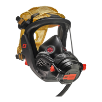
Testing the Sensor Module Lights
When performing operational testing on
respirator units equipped with a PASS device
(distress alarm), verify that the sensor
module lights are operating properly.
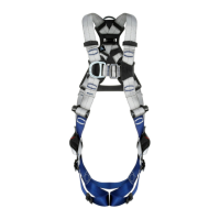
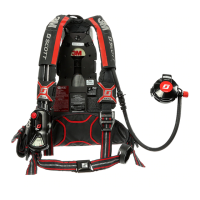
Figure 1-10 shows the sensor modules on the
respirator, and Table 1-2 on page 23
describes how the lights behave for
particular actions or situations.
For more information about the sensor
module lights, see the manual for the Scott
Electronic Management System (SEMS) II.
Figure 1-10 Sensor modules
Table 1-2 Operation of Sensor Module Lights
ACTION OR SITUATION BEHAVIOR OF LIGHTS
Start Air-Pak SCBA (i.e., open cylinder valve) Bright light, then flashing green light
Normal operation Flashing green light
Air cylinder between 1/2 and 1/3 full Flashing yellow light (2 quick flashes) every second
Air cylinder less than 1/3 full (low air) Flashing yellow light (alternately)
Low battery while unit is on Flashing yellow light once every 2 seconds
Shut down Off
Press reset button on control console with unit off
(battery test)
Good battery: Bright light, then flashing green light
Low battery: Bright light, then flashing red light
Press manual alarm button on control console with
unit off
Flashing red light (simultaneously)
Press reset button on control console during full
alarm
Flashing green light
PASS pre-alarm Flashing red light (alternately)
PASS full alarm Flashing red light (simultaneously)
TIP
The yellow light is a combination of the red, green, and white lights on the sensor module. At close range, the
individual lights may be visible.
Sensor Module
Sensor Module
 Loading...