3M™ MicroTouch™ Controller EX USB Reference Guide 11
3M Touch Systems, Inc. Proprietary Information -- 29489v05
Sensor Connection
The sensor cable has a 12-pin (2 x 6) dual row female connector that plugs into the
EX121 controller. Table 2 describes the pins on this connector. The sensor connector
always exits towards the USB cable.
Table 2. Sensor Cable Connector for EX121 Controllers
Pin Wire Color Description
1
——
OVRAM interface
2
——
OVRAM interface
3
——
OVRAM interface
4
—— +5 VDC
5
6
7
Gray
Green
Orange
ot used
Chassis (earth) ground
ot used
8 Brown Cable
shield/drain
wire
Connects to the flex tail shield, which must not be grounded
because the EX121 drives the flex tail shield with an AC
waveform.
9
10
11
12
White
Red
Black
Blue
Upper right (UR) corner
Lower right (LR) corner
Upper left (UL) corner
Lower left (LL) corner
The sensor flex tail has a 5-pin single row female connector that plugs into the EX111
controller with a right side tail exit. The following table describes the pins on this
connector.
Table 3. Sensor Flex Tail Connector for EX111 Controllers
Pin Description
1 Upper left (UL) corner
2 Upper right (UR) corner
3 Connects to the flex tail shield, which must not be grounded because the
EX111 drives the flex tail shield with an AC waveform.
4 Lower right (LR) corner
5 Lower left (LL) corner
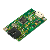
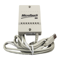
Mounting the Controller
The cased controller is mounted externally. The uncased controller is mounted internally.
Choose a convenient spot away from high-voltage, high power cables and electronics.
Use 4-40 plastic screws to mount the cased controller to eliminate possible ESD input
path. Metal or plastic screws can be used on the 2x3 board if the green ground wire is
used. Metal screws are required on the 1x2 board if a separate ground wire is not used.
The controller should be mounted in line with the sensor flex tail exit point to minimize
flexing. Refer to Figure 1 for more details on controller mounting.