Page 13
Each captured waveform contains:
traces of the wire signals at the port;
an indication of the event that triggered the capture;
the time-tag of the triggering event.
The waveform viewer software (see section 9.4, “Waveform Handling”) allows a waveform to be viewed at
various zoom levels, and saved to a file. This software interprets the recorded signal waveforms as SpaceWire
characters, and supplies a labelled time axis.
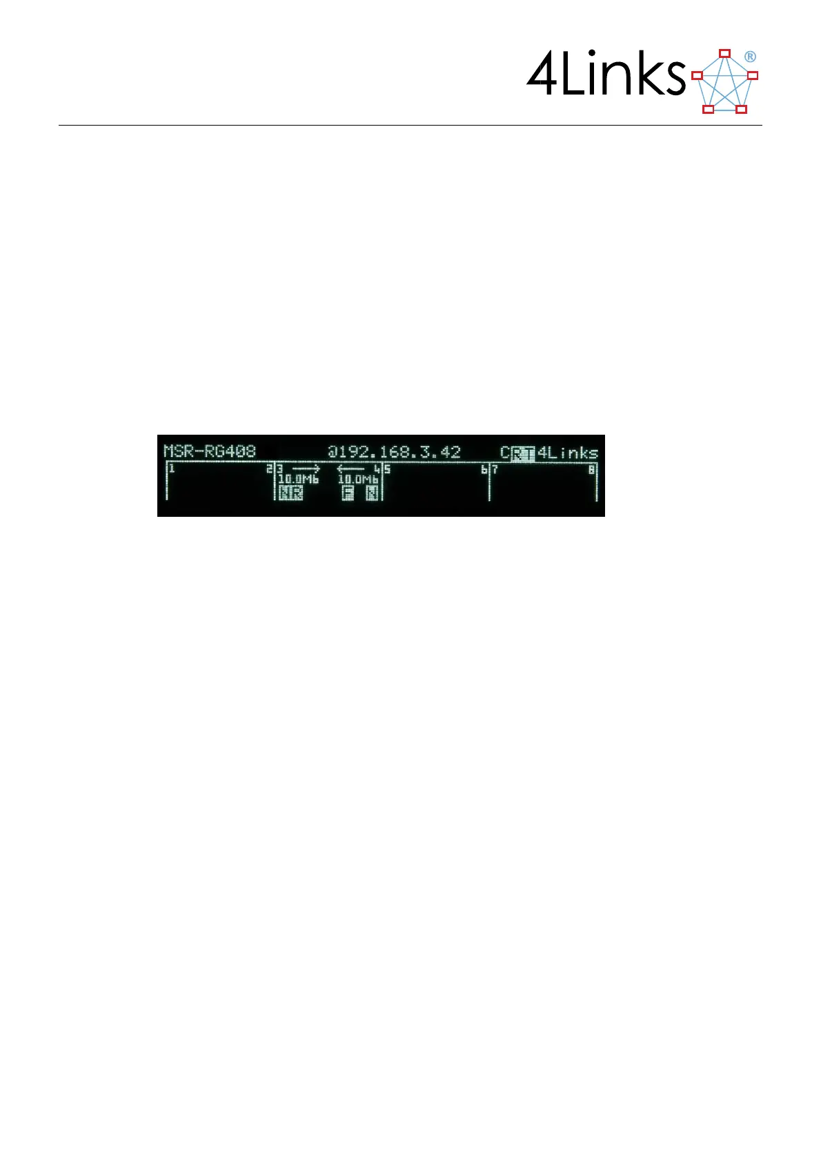
2.5. Front-Panel Display
The MSR’s front panel display continuously monitors and displays the states of the Ethernet and SpaceWire links.
The top line of the display shows the product number, the current IP address of the EtherSpaceLink unit, and the
name “4Links” on the right.
Figure 2.3: The MSR display
2.5.1. Ethernet information
Information about the remote Ethernet connection is shown on the upper section of the display. The status of the
Ethernet connection is provided, together with indications of when Ethernet transmit and receive activity occur.
2.5.2. SpaceWire information
Information about the SpaceWire links is shown on the lower section of the display. The speed of both directions
of each link is shown, and any receive or transmit activity is indicated.