Page 24
5. User Interface
5.1. Initial (power-up) display
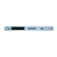
The front-panel display will initially show the unit proceeding through self-test and configuration, leading after a
few seconds to a normal operational display.
Figure 5.1: The RG408 power-up display
Failure during the initial four stages of the self-test usually indicates a hardware problem. Failure at the fifth stage
suggests a fault with the contents of the memory card; memory cards are configured for specific 4Links units, so
make sure that you have plugged the correct card into this unit.
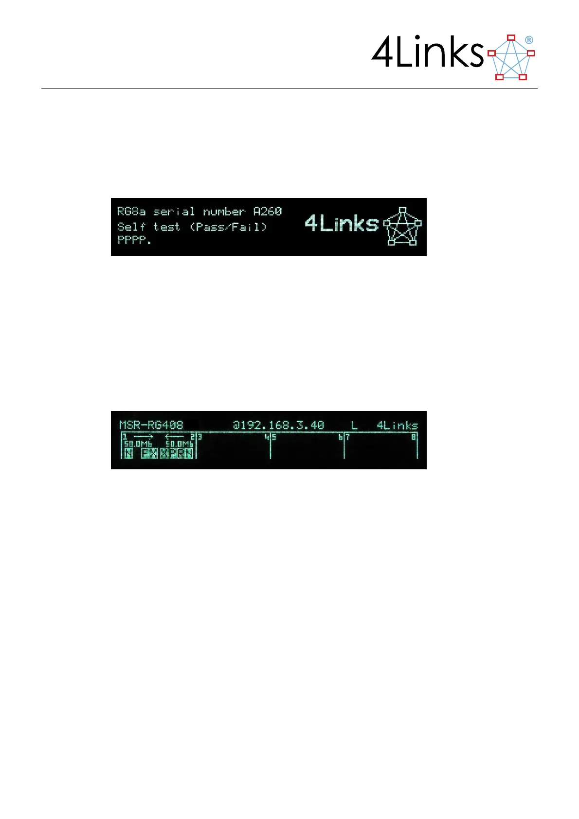
5.2. Normal (status) display
In normal operation, the display shows the state of the SpaceWire and Ethernet connections, and any activity on
these interfaces.
Figure 5.2: The MSR status display
The top line of the display shows Ethernet information:
The IP address of this unit;
Ethernet status:
∗ The SFP module (see section 3.2, “The Ethernet Connection”) is not present;
X The SFP module is present but the Ethernet cable is not connected;
L The Ethernet is connected and the MSR is listening for a connection;
C The Ethernet is connected to a user program.
Ethernet Activity (note that Ethernet activity that is not related directly to SpaceWire traffic may be
reported, e.g. broadcasts from other devices on the Ethernet):
R Data is being received from Ethernet;
T Data is being transmitted to Ethernet.