Page 17
3.2. The Ethernet Connection
An RJ45 socket, housed in an SFP module situated on the front panel, supports 1000 Mb/s (1000BaseT) or 100
Mb/s (100BaseT) full-duplex Ethernet connections over twisted-pair cable. The interface has an auto-crossover
function allowing direct connection of the EtherSpaceLink unit, with a standard or crossover cable, to a computer
or to an Ethernet hub or switch.
3.2.1. ICMP Echo (ping) Support
The MSR will respond to an ICMP echo request - as provided on Windows and Unix/Linux operating systems via
the ping command. This can provide a simple test to check that the unit is accessible on the network.
3.2.2. Full-Duplex Ethernet
Only full-duplex Ethernet connections are supported.
3.3. SMA Synchronization Connectors
Synchronization (to other 4Links units or to external devices) is achieved using SMA connectors, on units with the
“-S” model number suffix where they are fitted.
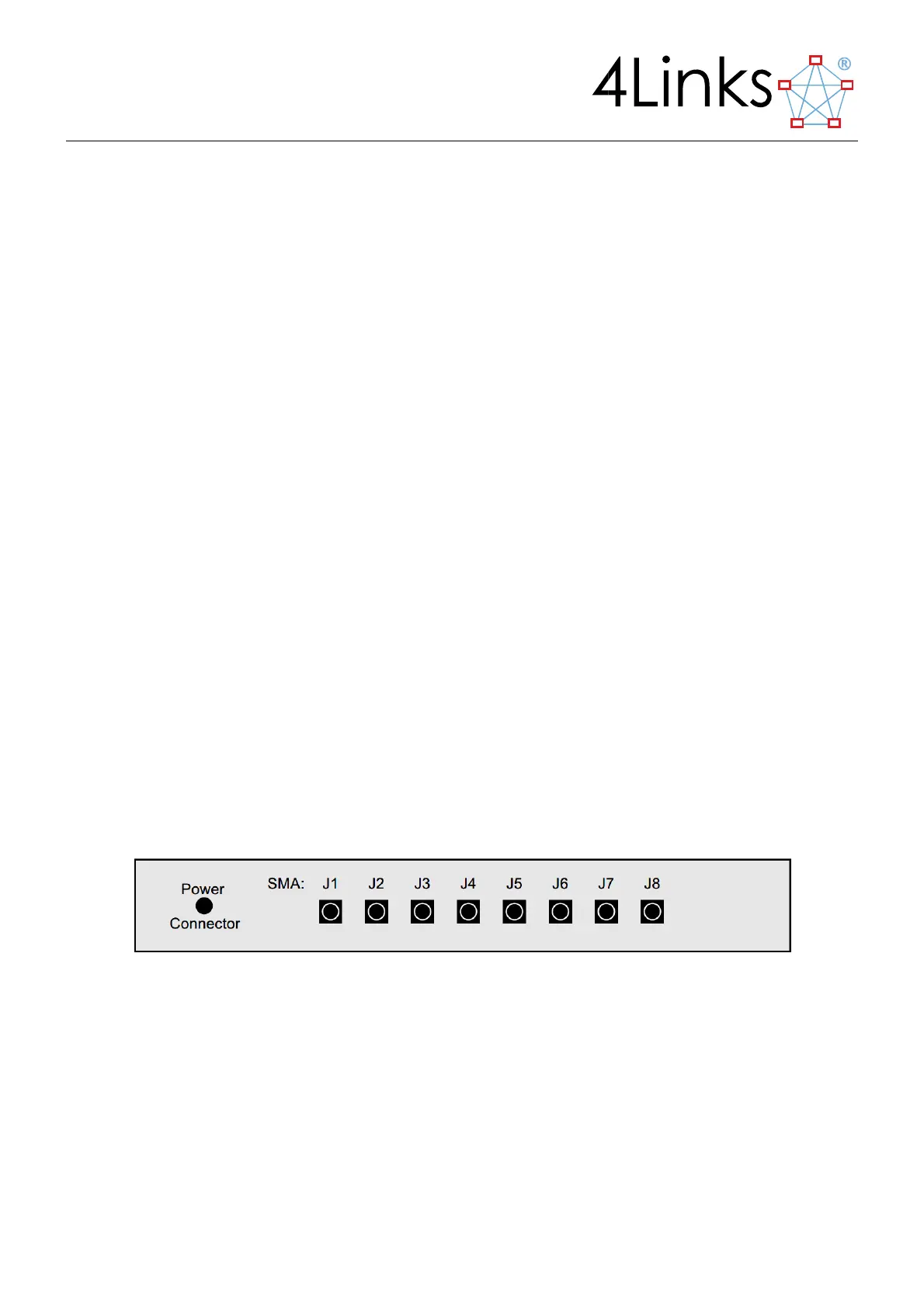
The rear panel of a suitably-equipped MSR contains eight SMA connectors, labelled J1 to J8 from left to right
when looking at the rear panel, corresponding to software and API synchronization connections J1-J8
respectively.
These connectors are used as four pairs, J1-J2, J3-J4, J5-J6 and J7-J8. Connector pairs J1-J2, J3-J6 or J7-J8 may not
be present on all platforms. Refer to the functions and options installed for details of their usage.
The outer conductor of each SMA connector is ground / shield, and the inner conductor carries the signal. The
two SMA connectors in a pair are internally wired to each other and may be used as a loop-through connection
for a 50 Ω-terminated line. Alternatively, a 50 Ω resistive terminator may be inserted into one of the connectors
in each pair so that the other forms a terminated connection.
Figure 3.2: SMA connector layout
Connector pair J7-J8 is used on the MSR for time synchronisation; see section 8, “Unit-to-Unit Time-Tag
Synchronisation”, for details.