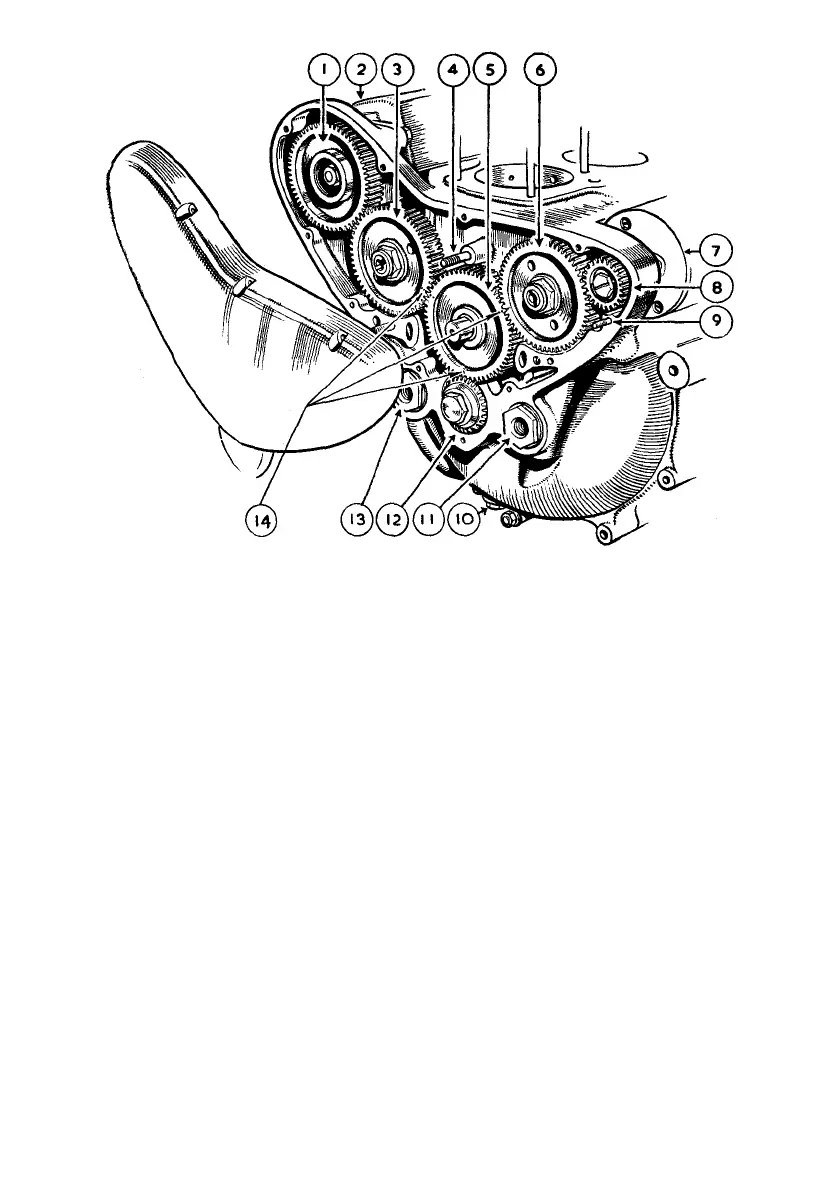
Illustration 21
Valve timing gear
The gears on the two camshafts (secured by nuts having left-hand threads) have to be
mechanically withdrawn and each has two holes drilled and threaded to accommodate
the two bolts of a bridge type extractor (part number 015374) which has a central bolt
threaded in the bridge. The two outside bolts are screwed into the holes in the gears
whereupon application of the centre bolt being screwed into the bridge bears on the
end of the shaft thereby causing the gear to be withdrawn.
The gear on the dynamo needs no extractor because the dynamo, complete with gear
assembled, is easily and quickly removed from the engine and the subsequent removal
of the gear from the dynamo shaft is a simple workshop operation.
ALTERNATOR TWINS
To remove distributor pinion, spring outwards the circlip, take out the parallel pin
passing through the pinion and distributor shaft—the pinion can then be removed.
1
2
3
4
5
6
7
8
GEAR WHEEL ON MAGNETO ARMATURE
SHAFT.
MAGNETO.
GEAR WHEEL ON INLET CAMSHAFT.
ONE OF THE THREE STUDS RETAINING
THE OIL PUMPS ASSEMBLY.
INTERMEDIATE (OR IDLE) GEAR.
GEAR WHEEL ON EXHAUST CAMSHAFT.
DYNAMO.
GEAR WHEEL ON DYNAMO ARMATURE
SHAFT.
9
10
11
12
13
14
STUD, IN DYNAMO BODY A N D PASSING
THROUGH CRANKCASE AN D TIMING
GEAR COVER.
CRANKCASE DRAIN PLUG.
ADAPTOR TO ACCOMMODATE OIL FEED
PIPE BANJO PIN.
TIMING PINION ON CRANKSHAFT.
ADAPTOR TO ACCOMMODATE OIL
RETURN PIPE BANJO PIN.
MARKS TO SET TIMING.
See page 96 for particulars of special timing disc graduated in degrees.