9
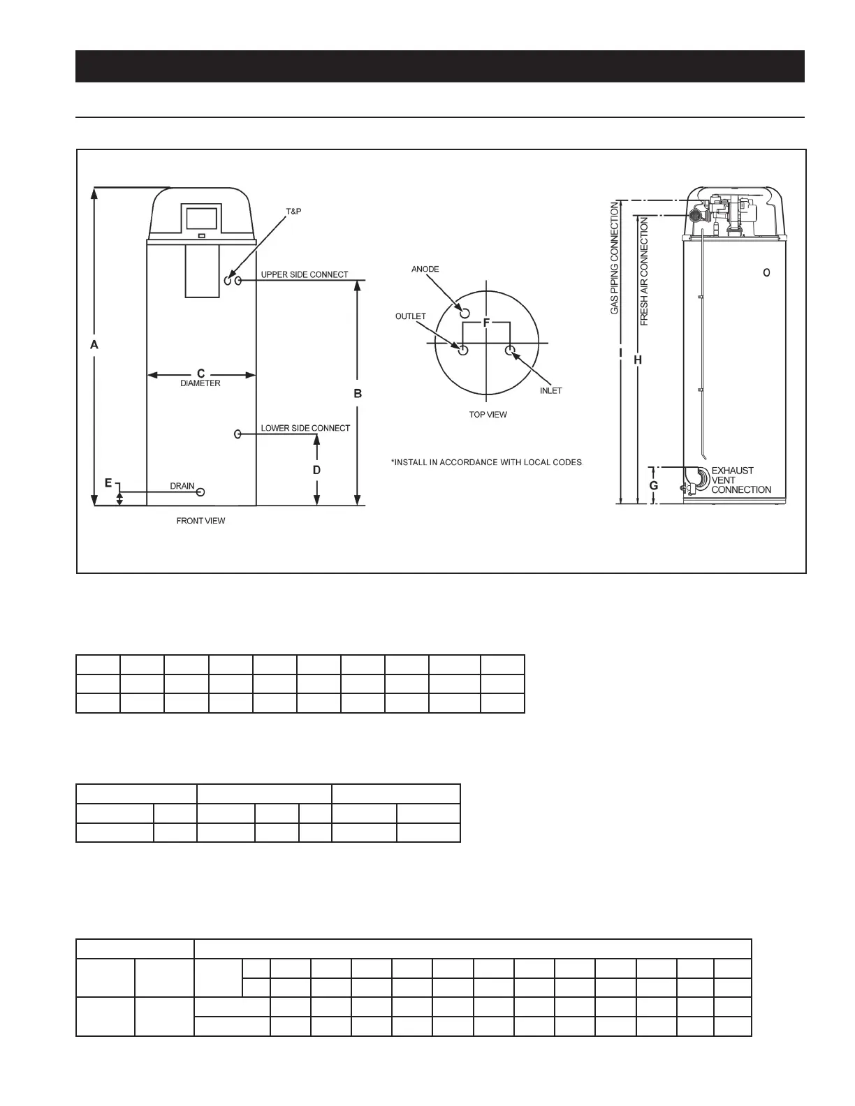
TABLE 1 – Rough-In-Dimensions
Units A B C D E F G H I
Inches 66.75 49.25 22.00 15.75 3.00 8.00 8.00 62.00 65.00
cm 169.5 125.09 55.88 40.00 7.62 20.32 20.32 157.48 165.1
Top/Side Inlet and Outlet: 3/4” NPT
Gas Inlet: 1/2” NPT
TABLE 2 – Capacity, Gas and Electrical Characteristics
Approximate Capacity Manifold Pressure Electrical Characteristics
U.S. Gals. Liters Gas Type “WC kPA Volts/Hz Amperes
50 189 Nat./LP 0” 0” 120/60 <5
All models - Maximum Supply Pressure: 14 inches W.C. (3.48kPa)
Minimum Supply Pressure for Natural Gas: 3.50” (.87kPa)
Minimum Supply Pressure for Propane Gas: 8.00” (1.99kPa)
Minimum pressure must be maintained under both load and no load (dynamic and static) conditions.
TABLE 3 – Recovery Capacities - U.S. Gallons/Hr. and Liters/Hr. at Temperature Rise Indicated
Input Recovery Capacities
Rating
(Btu/hr)
Rating
(kW)
Temp.
Rise
F 30 40 50 60 70 80 90 100 110 120 130 140
C 17 22 28 33 39 44 50 56 61 67 72 78
100,000 29.3
GPH 387 291 233 194 166 145 129 116 106 97 90 83
LPH 1465 1102 882 734 628 549 488 439 401 367 341 314
Recovery capacity based on 96% thermal efciency
ROUGH IN DIMENSIONS
FIGURE 1A.
INSTALLATION CONSIDERATION