17 Page
240 (T-H3J), 340 (T-H3S) and 540 (T-H3) models Service Manial
Ver. 1.00
CONFIDENTIAL
Check-
point
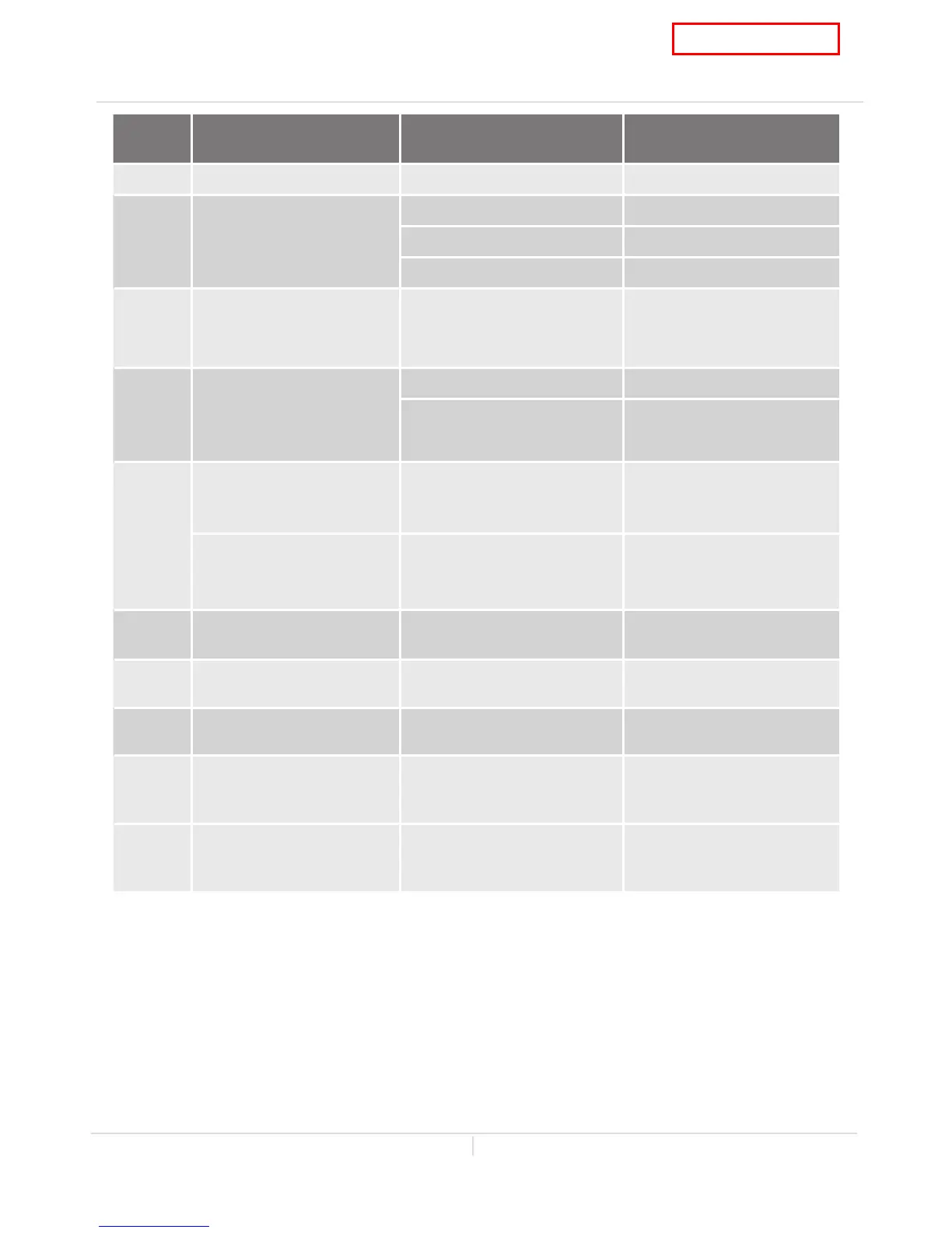
Part and Description Color of wires Normal range
F Remote controller White – Black 11 to 25 VDC
G Fan motor
Red - Blue 132 to 192 VDC
Yellow - Blue 13 to 17 VDC
Orange - Blue 2.0 to 6.5 VDC
H1 Gas proportional valve White - red
1.0 to 15 VDC
(during operation)
and
20 to 40 Ω
H2 Flow sensor
Red - Black 4.0 to 5.5 VDC
White - Black
1.0 to 4.0 VDC (pulse)
1,080 pulse / min
(more than 18 Hz)
I
Air-fuel ratio rod
Yellow - AFR rod
(Between the AFR rod and
the computer board)
More than 1 μA
(during operation)
Flame rod
Orange - Flame rod
(Between the flame rod and
the computer board)
More than 1 μA
(during operation)
J Flow adjustment valve Red - Black
7.0 to 16 VDC and
0.09 to 0.2 kΩ
J1
Bypass valve
540 (T-H3) models only
Brown - Red
3.0 to 11 VDC and
50 to 85 Ω
K1 Exhaust thermisator White - White See table on p. 19
K2 Hi-limit switch for exhaust White - White
Less than 1 VDC
and
less than 1.0 Ω
L Temperature controller White – Black 11 to 25 VDC
 Loading...