16 Page
240 (T-H3J), 340 (T-H3S) and 540 (T-H3) models Service Manial
Ver. 1.00
CONFIDENTIAL
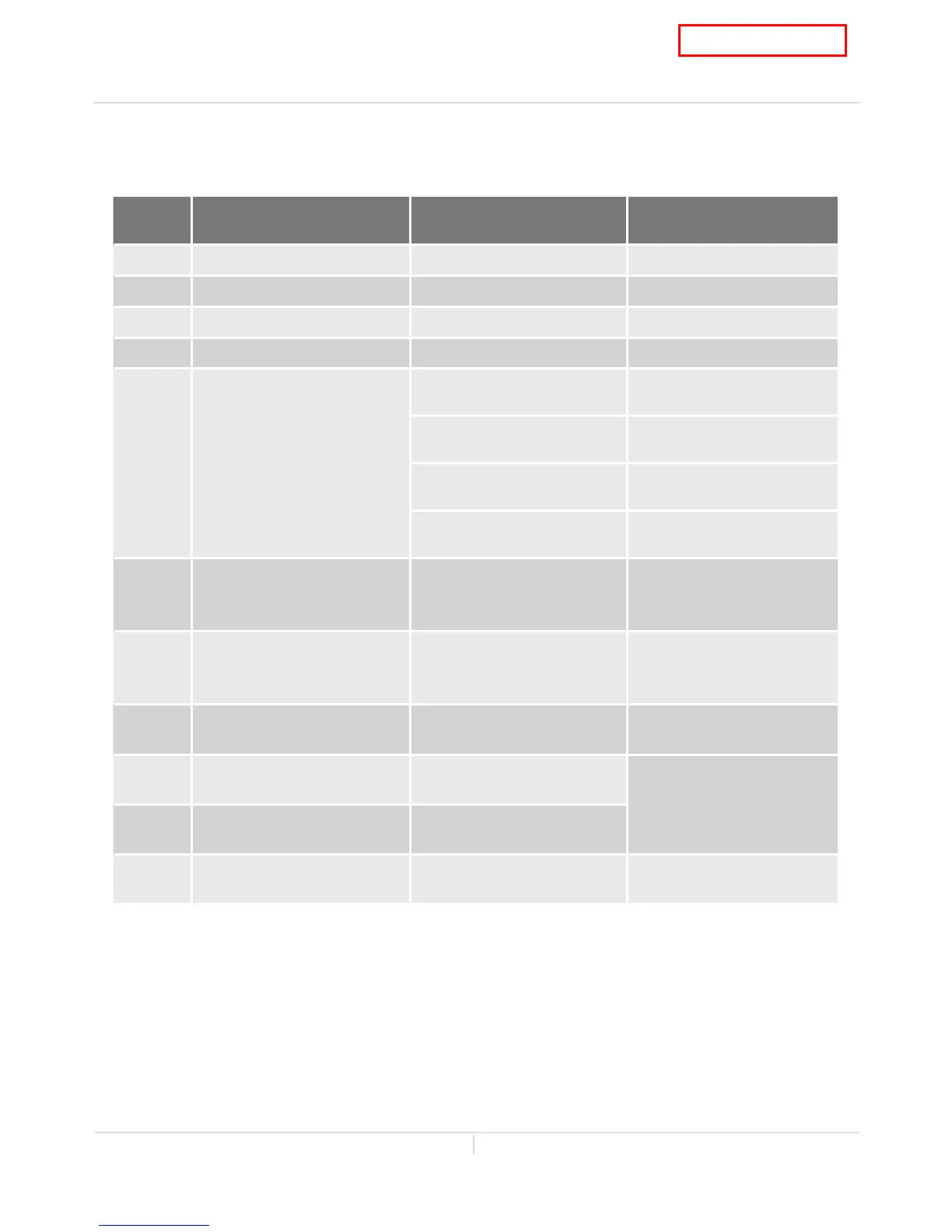
7. Wiring diagram check points for diagnosis
The table below applies to both the the Direct Vent Indoor models and Outdoor models.
Check-
point
Part and Description Color of wires Normal range
A 120V Power supply White – Black 108 to 132 VAC
A1, A2 120V Power supply Black - White 108 to 132 VAC
B Igniter Purple - Purple 108 to 132 VAC
B1 Heater Yellow - Yellow 108 to 132 VAC
C Gas valves
Light blue - blue at COM (MV)
93 to 120 VDC (during
operation) / 1.35 to 1.65 kΩ
Green - blue at COM (SV1)
93 to 120 VDC (during
operation) / 1.35 to 1.65 kΩ
Orange - blue at COM (SV2)
93 to 120 VDC (during
operation) / 1.35 to 1.65 kΩ
Red - blue at COM (SV3)
93 to 120 VDC (during
operation) / 2.07 to 2.53 kΩ
C1 Hi-limit switch Blue - Blue
Less than 1 VDC
and
less than 1.0 Ω
C2 Overheat cutoff fuse Blue - Blue
Less than 1 VDC
and
less than 1.0 Ω
D1, D2
Easy-link connectors
540 (T-H3) models only
Black - White
15 VDC
(during Easy-link operation)
E1 Outlet thermistor Black - Black
See table on p. 18
E2 Inlet thermistor Black - Black
E3
Heat exchanger thermistor
540 (T-H3) models only
Black - Black See table on p. 19
 Loading...