20 Page
240 (T-H3J), 340 (T-H3S) and 540 (T-H3) models Service Manial
Ver. 1.00
CONFIDENTIAL
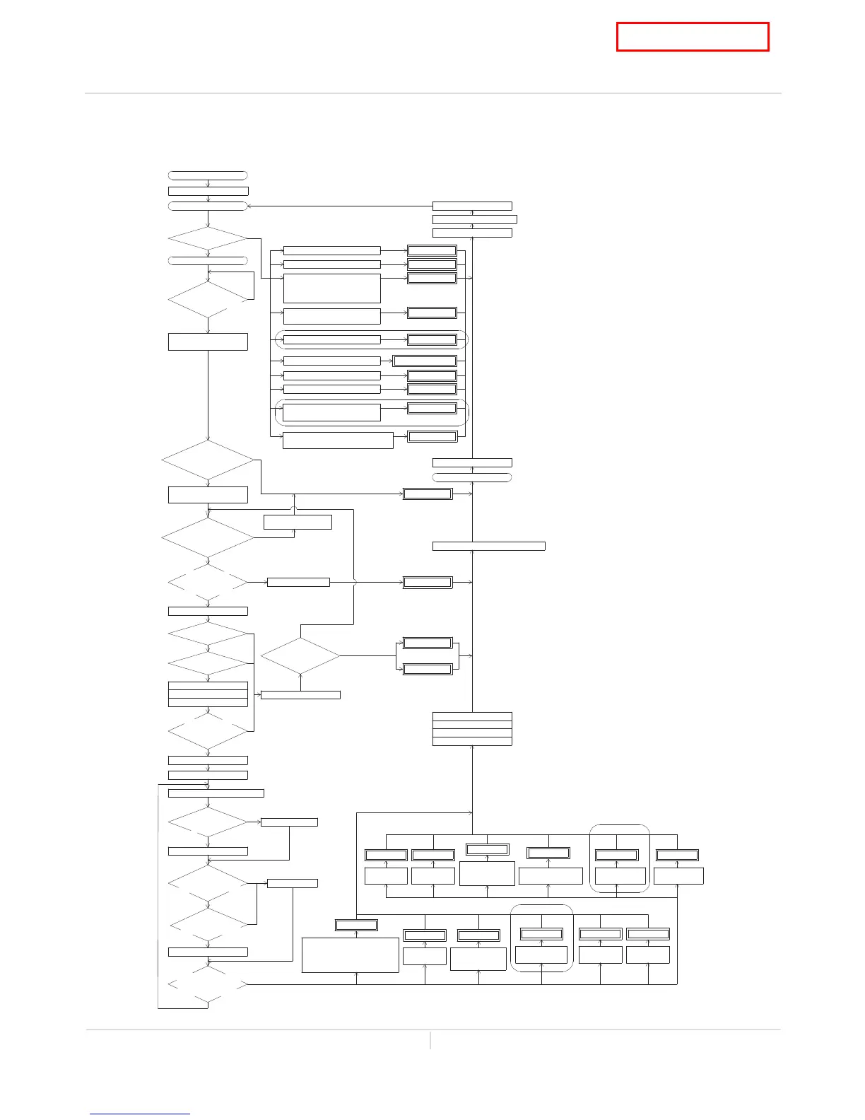
9. Operational flow chart
The diagram below refers to both the Direct Vent Indoor models and Outdoor models.
Power supply ON
Operaon SW ON
FAV&BV open
Pre-check
NORMAL?
Faucet opens
Water Flow
Above 0.5GPM?
FM speed
(Below
1,000rpm?)
Fan moter start
operaon
Flame rod
DC0.15
μA?
Igniter ON
Hi-limit
Normal?
OHCF
Normal?
MV ON
SV2 ON
GPV ON
Flame rod
detects Above
DC1.0μ
A?
Burning lamp ON
Igniter OFF
Proporonal control
BTU
change over
point?
SV1 SV3 ON
Below water
heat capability?
FAV OPEN
Safety devices
sensed
abnormal condion
FAV close
SV1 SV3 OFF
False Dipswitch sengs
InTH failure
PCB failure
MV circuit failure
031 blink
321 blink
701 or 771 blink
510 blink
611 blink
Fan motor stop
operaon
721 blink
False flame
Igniter OFF
Reignion
Success?
MV OFF
SV2 OFF
GPV OFF
SV1 SV3 OFF
Fan motor stop operaon
Faucet closes
Flow sensor OFF
Remove cause
Opearon lamp OFF
Operaon stop
YES
NO
YES
NO
NO
YES
YES
NO
(20sec later)
YES
NO
NO
YES
YES
NO
YES
NO
(5sec later)
YES
YES
NO
YES
NO
(20sec later)
YES
NO
NO
NO
YES
FM speed
(Above
1,000rpm?)
Below
Max flow rate
restricon?
111 blink
121 blink
341 blink
311 blink
OuTH failure
311 blink
OuTH failure
331 blink
Flame
blows out
OHCF melted
(above 430
゜
F)
AFR rod
failure
Abnormal
burning
121 blink
121 blink
991 blink
391 blink
BV modulates
Flow&temp
321 blink
InTH OPEN
or SHORT
331 blink
OuTH OPEN
or SHORT
detects Below
FAV ; Flow Adjustment Valve
B V ; Bypass Valve
F M ; Fan Motor
OHCF; Over Heat Cut-off Fuse
M V ; Main gas Valve
SV1 ; Solenoid Valve 1 (See the secon 6)
SV2 ; Solenoid Valve 2 (See the secon 6)
SV3 ; Solenoid Valve 3 (See the secon 6)
GPV ; Gas Proporonal Valve
InTH; Inlet thermistor
OuTH; Outlet thermistor
Heat exchangerTH; Heat exchanger thermistor
Exhaust TH; Exhaust thermistor
PCB ; Print Circuit board
(Computer board)
AFR ; Air Fuel Rao rod
(Only 540 (T-H3) models)
(Only 240 (T-H3J) / 240 (T-H3S) models)
PCB
failure
711 blink
Exhaust
temp. failure
941 blink
*
SV circuit failure
551 blink
Thermistor or HL switch
for exhaust gas failure
941 blink
Fault of flow adjustmentvalve
651 blink
*NOTE
The "341" and "941" error code are
enabled in the Direct Vent Indoor models.
Heat exchanger TH failure
(Only 540 (T-H3) models)
ExhaustTH failure
341 blink
Fan motor
fault
611 blink
OuTH OPEN or SHORT
(Only 240 (T-H3J) / 240 (T-H3S) models)
Heat exchanger TH OPEN
(Only 540 (T-H3) models)
ExhaustTH
OPEN or SHORT
*
(Only 540 (T-H3) models)
(Only Easy-link system)
Fault of
bypass valve
661 blink
(Only 540 (T-H3) models)
or SHORT
 Loading...