Installation and Service Manual Upsilon-Series
32
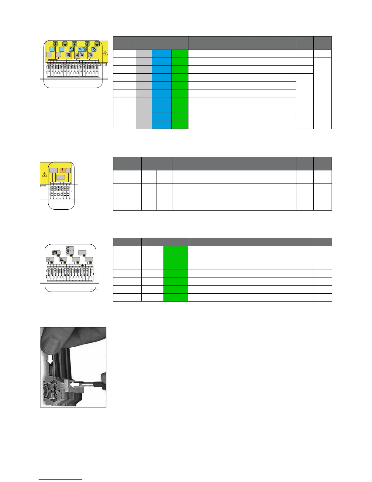
1. High voltage supply: 16 Connections
Position Connection Application
PG
Max.
V/A
1, 2, 3 Live Neutral Earth Power for boiler. Power cable not supplied 13,5* 230V
4, 5, 6 Live Neutral Earth Output 13,5
230V
4A
7, 8, 9 Live Neutral Earth System pump P3 13,5
10 Live Three-way valve to CH
13,5
11 Live Three-way valve to DHW or DHW pump P2
12 Neutral Three-way valve or DHW pump P2
13 Earth Three-way valve or DHW pump P2
14 Live DHW load pump P4
13,515 Neutral DHW load pump P4
16 Earth DHW load pump P4
2. High voltage switches: 6 Connections
Position Connection Application
PG
Max.
V/A
1, 2 1 2 Relay output fault signal 13,5
230V
5A
3, 4 3 4 Relay output heat demand 13,5
230V
5A
5, 6 5 6 Relay output external heat source / 2nd propane gas valve 13,5
230V
5A
3. Low voltage sensors: 16 Connections
Position Connection Application Tulles
1, 2 1 2 Hot water sensor T3 IP67
3, 4 3 4 Outdoor sensor T4 (advice) n.a. at 0-10V IP67
5, 6 5 6 Common ow sensor T10** (must be connected) IP67
7, 8 7 8 On-Off contact / Open Therm contact (auto detect) IP67
9, 10 9 10 0 -10 Volt input (temperature or load) IP67
11, 12 11 12 Blocking contact (bridge mounted) IP67
13, 14 13 14 Low water pressure switch off contact NO
(function not active) IP67
* PG glands for cable duct already assembled in the factory. For a few connections, some
PG glands are supplied separately.
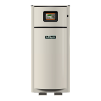
The maximum cable diameter for the terminals is 2.5mm
2
Connect the cable by pushing down the control on the terminal strip using a at screw-
driver (refer to g. 8.e).