12
the temperature is less than the operating setpoint minus the
differential temperature and the thermostat input is closed then
a call for heat is established and the system shifts to the run
mode (green “Running” LED turns on).
5. The heating sequence begins by applying power to the pump.
6. After a few seconds the blower is turned on for 30-second
pre-purge period of combustion chamber.
7. The igniter is turned on.
8. After the igniter has reached a minimum of 2.8 amps, the gas
valveisenergizedtoallowgasowtoburner.
9. After an additional one second, the system checks the status
oftheamethroughtheamerod(sensor).Iftheameisnot
veriedwithin4seconds,thegasvalveisimmediatelyshut
off followed by 15-second inter-purge period, then the system
returns to step 7, if the “Trial for Ignition” dipswitch is set for
three (3) tries. If the dipswitch is set for one (1) trial, the system
will declare an error and boiler will require resetting the control.
10. Theboilerwillremainrunninguntilthesetpointissatised.
Once satised, the blower will continue for 15-second post
purge period.
11. Oncesetpointhashavebeensatised,theboilerpumpwill
continue to run for the programmed post-circulate cycle.
12. The control now enters the idle state as displayed by the
“Standby” LED. The control will continue to monitor heat
demand and state of other system devices. Upon a drop of
water temperature below the set parameters, the control will
return to step 5 and repeat the entire operating cycle. Note:
Any fault detection, during standby or running modes, will halt
the heating sequence and shift the system to the service mode
where the detected fault will be displayed.
NOTE: In standby and running modes the system constantly
monitors the signals and the internal operation for faults. Any
detected fault will halt the heating sequence and shift the system
to the service mode, where the detected fault will be displayed.
TEMPERATURE SETPOINTS (SYSTEM CONTROL ALGORITHM)
The boiler has a hysteresis type control, which means that it will
begin heating the water when the temperature sensed by the
control probe (inlet or tank) falls below the operating setpoint minus
the differential setpoint. It will stop heating the water when the
temperature rises to the operating setpoint.
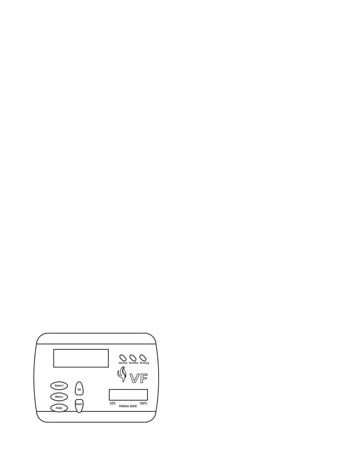
UIM OPERATING PROCEDURES
FIGURE 2. - UIM, USER INTERFACE MODULE
The UIM receives commands from the user and displays operational
information to the user via an LCD (liquid crystal display) up to eleven
LED’s,andvetouchswitches.TheLCDprovidesinformationto
the user by the use of 10 menu-activated screens. Within each of
the screens, helpful information can be displayed by pressing the
“Help” button. The LED’s visually inform the user about the mode
the system is in. The touch switches allow the user to control the
operation of the system. The operation of these parts is described
in the following section:
UIM Screens:
On all screens a double vertical bar appears on the right side of
the display each time a key is touched to indicate that a key has
been activated. On several screens an indicator “>” appears on
the left side of the display to indicate the active line. The “Up/
Down” keys are used to move the indicator to the desired line and
the “Select” key is pressed to select the line. Also, on most of the
screens, up/down arrows appear on the right side of the screen
to indicate that there is additional lines either above or below the
displayed four lines.
• Menu Screen:
Displayed when the user presses the “Menu” key. This screen
is the selection point for the other 9 screens.
• Temperature Screen:
Displays the sensed temperatures of the Outlet, Inlet, and
Tank probes. Also displayed is the calculated Delta T (Outlet
minus Inlet) for the system. Shorted (“Short”) and disconnected
(“----”) probes are also displayed.
• System Status Screen:
This screen is used to view the status of switch inputs and output
states. An asterisk (*) is displayed next to the label when the
status is “True” (the description is fullled). For example, if
waterisowing,ordetectedbytheowsensor,thenan“*”will
appear in front of the Flow label (i.e. *Flow). Another example
would be the ECO switch. If the outlet temperature is too high
the display will show: *ECO.
The System monitors the inputs at these times:
• ECO,BlockedFlue,LowGas,HiLimit,andHiGas-atalltimes
for a fault condition.
• Tstat-atalltimesforopen/closedconditions.
• Flow - for an on condition when the pump is on (no check for off
state)
• BlowerProver-whentheBlowerison.
• IgniterCurrent-foranonconditionapproximately18seconds
after the Igniter is turned on until the igniter is turned off and an
off condition at all other times.
• Flame-foranonconditionapproximately5secondsafterthe
gas valve is turned on until the valve is turned off and at all other
times for an off condition.
Control Status Screen:
Displays the status that the MCB micros are in. The MCB has
5 possible states and the FCB have 9. The normal MCB states
sequence is to move from Idle to Pre-Circulate when a call for
heatisinitiated.OnceheathasbeensatisedortheThermostat
is opened, the sequence moves to Post-Circulate and then back to
Idle. If a fault occurs at any time, the process jumps out of sequence
and goes directly to the appropriate Hard or Soft Fault state.
Description of MCB control states:
• Idle:
The yellow “Standby” LED is turned on and the system