MUA II Controller 3
Technical Guide
Features
The MUA II Controller Board is designed with 5 usable analog inputs,
and 5 relay outputs. The controllers input and output capabilities can
be expanded by use of either 2 slot or 4 slot expansion boards that plug
into the MUA II Controller by means of a modular cable. The MUA II
Controller is designed for used with Makeup Air HVAC units. Features
include the following:
• Up to 8 Stages of Cooling (4 on board, 4 more with
expansion board)
• Up to 8 Stages of Heating (4 on board, 4 more with
expansion board)
• External Modulating Heat
• Fan Proving Interlock
• Supply Air Setpoint Reset From Temperature Input
• Dewpoint Setpoint Reset From Humidity Input
• Accepts Remote Occupied Signal
Controller Overview
• De-Humidification Capable
• 7 Day, 2 Event per Day Scheduler Built In
• 14 Day Holiday Scheduler Built In
• Internal Trend Logging
• Direct Connection With MODGAS II And REHEAT II
Controllers
Most makeup air control configurations can be configured with the
standard MUA II Controller. If the application requires more outputs,
optional relay expansion boards are available from the factory to provide
for additional relay outputs as required. These expansion boards are
installed on eithMUA II Controller board via a modular cable connection.
The available expansion board configurations allow for up to 16
additional binary (relay) outputs. The various expansion boards connect
to the expansion board base. Jumpers must be set according to the
board type installed. Up to 4 Relay Output Expansion Boards can be
installed on the expansion base board connected to the controller.
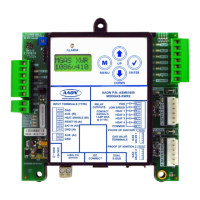
Figure 1: MUA II Controller Dimensions
RLY1
D1
D2
D3
D4
D5
CX3
RAM
EPROM
C3
C2
U6
CX6
C1
CX2
U2
U3
PAL
CX4
U4
TUC-5R PLUS
YS101816 REV. 2
V1
V2
V3
V5
V4
TB2
4
NETWORK
TOKEN
16
32
8
SW1
ADD
2
1
ADDRESS
V6
POWER
GND
24VAC
L1
D16
R6
C9
SC1
R11
U11
D13
C16
VR2
TB4
R27
C13
R10
VR1
C19
C18
U8
CX8
U9
X1
R7
D10
R13
D12
C7
CX10
U10
CX12
U12
U14
CX14
PJ3
PJ2
PJ1
EXPANSION
PRESSURE
SENSOR
T'STAT
C17
D15
R26
C20
R25
R24
R22
U15
CX13
U13
C15
R19
R15
C14
D18
D17
PU1
PU2
PU3
PU4
PU5
PU7
D6
D7
D8
D9
D11
D14
C12
C10
0-5
VDC
0-1
VDC
JP1
C11
X2
GND
TB3
INPUTS
GND
GND
+VDC
AIN1
AIN2
AIN3
AIN4
AIN5
AOUT1
AOUT2
AIN7
RN4
1
RN5
RS-485
CX5
U5
R
TB1
SHLD
T
COMM
COMM
RN3
1
RN1
U1
CX1
1
LD6
COMM
PWR
LD7
LED1
LED2
LD9
LD8
R1
U7
RV1
VREF ADJ
R28
+VREF
5.11V
TEST POINT
EWDOG
D19
RN2
1
COM1-3
COM4-5
R5
R4
R3
R2
R1
RLY2
RLY3
RLY4
RLY5
CX15
(1 MEG)
HH
P1
C21
6.2“
6.6”
7.3”
6.7”
.20 Dia.
Typ. of 4

 Loading...