Do you have a question about the AAON VCCX2 and is the answer not in the manual?
Details the capabilities, applications, and key features of the VCCX2 Controller.
Describes various HVAC applications supported by the VCCX2 Controller, including VAV and MUA units.
Lists part numbers for the VCCX2 controller and its associated expansion modules and accessories.
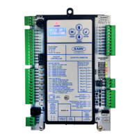
Identifies and labels the key components, terminals, and LEDs on the VCCX2 Controller.
Provides physical dimensions and mounting details for the VCCX2 Controller.
Provides physical dimensions and mounting details for the VCC-X EM1 Expansion Module.
Provides physical dimensions and mounting details for the 12 Relay E-BUS Expansion Module.
Covers crucial electrical, environmental, and safety factors for VCCX2 wiring.
Illustrates how to connect various input sensors and devices to the VCCX2 Controller.
Illustrates how to connect various output devices and actuators to the VCCX2 Controller.
Shows input and output wiring for the VCC-X EM1 Expansion Module.
Details wiring connections for the 12 Relay E-BUS Expansion Module.
Details wiring for connecting airflow measurement digital transmitters to the VCCX2.
Guides on applying power, initial checks, and configuring the VCCX2 Controller.
Provides maps of analog and binary inputs/outputs for VCCX2 and EM1 modules.
Details input/output maps specifically for the EM1 Expansion Module.
Explains the function and usage of VCCX2 controller's analog and binary inputs and outputs.
Details the functions of EM1 module's analog inputs, outputs, and binary inputs.
Lists and describes the various functions for user-configurable relay outputs.
Outlines various configuration options for system modes like fan, HVAC source, and occupied/unoccupied modes.
Describes general HVAC modes like Cooling, Heating, Vent, Dehumidification, and Economizer.
Covers Heat Pump, MUA, VAV, pressure control, and other specific operational features.
Explains the function of various LEDs on the VCCX2 Controller and expansion modules.
Details alarms for sensor failures, mechanical failures, direct fire, and compressor issues.
Provides instructions and tables for testing temperature and pressure sensors.
Explains trend logs, decoding bit strings, and specific module logs.
Describes different system configuration options: Stand-Alone, Interconnected, and Networked.
Illustrates typical stand-alone, single loop, and multiple loop networked system diagrams.
Explains the LCD display interface and navigation/editing key functions.
Details Main Screens Map, Settings, Status, Alarms, and Output Override screens.
Explains how to connect the VCCX2 controller to an MS/TP network.
Lists and describes analog input parameters and their BACnet objects.
Lists and describes analog value parameters, setpoints, and their BACnet objects.
Lists and describes binary input parameters and their BACnet objects.
Explains enumerated fields for control modes and bit strings for status.
Provides BACnet conformance statement details for controller versions.
| Brand | AAON |
|---|---|
| Model | VCCX2 |
| Category | Controller |
| Language | English |