20VCCX2 Controller Technical Guide
WIRING
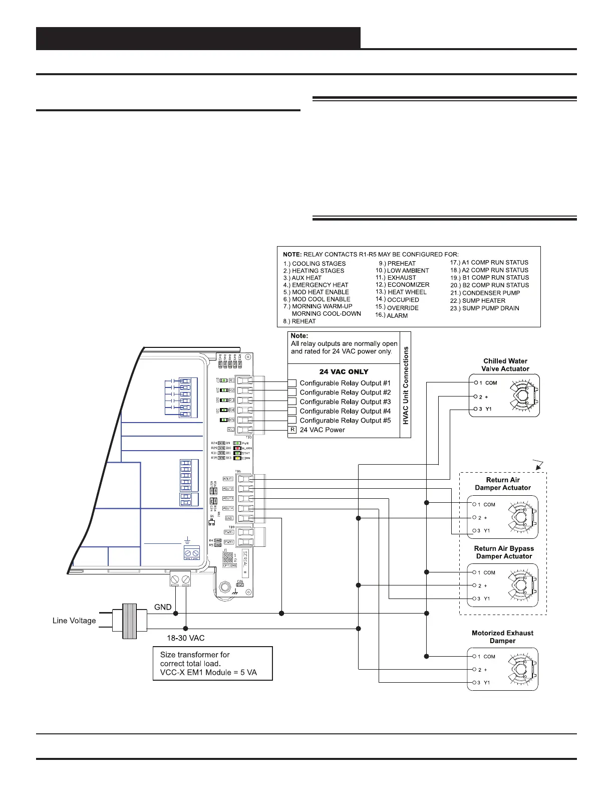
VCC-X EM1 Expansion Module
Outputs
The VCC-X EM1 Expansion Module must be connected to 24VAC
as shown in the wiring diagram below. Please see Table 1, page 15,
for correct VA requirements to use when sizing the transformer(s)
used for powering the expansion module.
Also, please note that when wiring the VCC-X EM1 Expansion
Module, its contacts must be wired as wet contacts (connected to
24VAC).
See Figure 10, this page, for output wiring.
(for Return Plenum Pressure
Control Applications)
Belimo Actuator wiring
shown. Consult factory
for other manufacturer
wiring instructions.
1 amp maximum load.
+24 VAC
GND
RELAY CONTACT
RATING IS 1 AMP
MAX @ 24 VAC
R1
R2
R3
R4
R5
RELAY OUTPUT
TERMINALS
ANALOG OUTPUT TERMINALS
GND
NOT USED
NOT USED
RETURN DAMPER
RETURN BYPASS
CHILLED WATER
EXH. DAMPER
ENTERING WATER
GND
+5V
GND
GND
GND
E-BUS
CONNECT
E-BUS
CONNECT
24 VAC POWER ONLY
WARNING! POLARITY
MUST BE OBSERVED
OR THE CONTROLLER
WILL BE DAMAGED
POWER INPUT
TERMINAL BLOCK
PRESSURE SENSOR
INPUT TERMINALS
BINARY INPUT
TERMINALS
TEMPERATURE SENSOR
TERMINALS
www.aaon.com
VCC-X EM1 EXPANSION
AAON P/N: ASM01691
RETURN/EXHAUST POF
DIRECT FIRE STATUS SIGNAL
MID SWITCH
MIXED AIR
ECONO FEEDBACK
EXHAUST DUCT
STATIC
LABEL P/N:
G040660
RC
J3
0-10 V
0-5 V
RA PLENUM
DIRECT FIRE ALARM SIGNAL
WARNING: Observe polarity! All boards must be wired
with GND-to-GND and 24 VAC-to-24
VAC. Failure to observe polarity will result
in damage to one or more of the boards.
Expansion modules must be wired in such
a way that the expansion modules and the
controller are always powered together. Loss
of power to the expansion module will cause
the controller to become inoperative until
power is restored to the expansion module .
Figure 10: VCC-X EM1 Expansion Module Output Wiring