Do you have a question about the AAON VCCX-IP and is the answer not in the manual?
Details the VCCX-IP Controller's capabilities, applications, and key features including digital compressors, VFDs, and advanced functions.
Explains various HVAC applications supported by the VCCX-IP Controller, such as VAV, space temperature control, and MUA units.
Lists part numbers for the VCCX-IP Controller and various expansion modules and accessories.
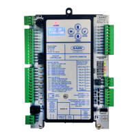
Identifies and describes the various hardware components and connection terminals on the VCCX-IP Controller board.
Provides detailed physical dimensions and measurements for the VCCX-IP Controller unit.
Details the physical dimensions and measurements for the VCC-X EM1 Expansion Module.
Provides the physical dimensions and measurements for the 12 Relay E-BUS Expansion Module.
Covers crucial wiring guidelines, voltage/environment requirements, and polarity warnings for installation.
Illustrates the input wiring connections for the VCCX-IP Controller, including sensors and binary inputs.
Details the output wiring connections for the VCCX-IP Controller, including relay and analog outputs for HVAC control.
Explains general wiring for the VCC-X EM1 Expansion Module, covering temperature, pressure, and proof of flow sensors.
Details wiring for EM1 exhaust duct static pressure and economizer actuator feedback connections.
Illustrates output wiring for the VCC-X EM1 Expansion Module, including relay and analog outputs.
Covers wiring details for the 12 Relay E-BUS Expansion Module, including relay outputs and E-BUS connections.
Explains wiring for airflow stations, including EBTRON, GreenTrol, and Paragon transmitters via E-BUS Adapter Board.
Guides on applying power, performing initial checks, and configuring the VCCX-IP Controller using operator interfaces.
Provides maps and tables detailing the analog and binary inputs/outputs for the VCCX-IP Controller and EM1 Module.
Details the specific analog and binary inputs/outputs for the EM1 Expansion Module, including relay outputs.
Provides detailed descriptions of the VCCX-IP Controller's analog and binary inputs and their functions.
Describes analog outputs (VFD, damper control) and user-configurable relay outputs of the VCCX-IP Controller.
Details the analog and binary inputs/outputs for the EM1 Expansion Module, including relay outputs.
Lists and describes the various functions that user-configurable relays (RLY2-RLY8) on the VCCX-IP Controller can perform.
Details various configuration options for Supply Fan, HVAC Source, Occupied/Unoccupied Modes, and HVAC Mode Set by Remote Contact.
Explains the different HVAC modes of operation, including Cooling, Heating, Vent, Dehumidification, and Purge modes.
Lists and describes the available trend log parameters for the VCCX-IP Controller, including status and sensor readings.
Details trend log parameters for RSMV, RSMD, and RSMZ modules, covering compressor and condenser status.
Explains how to interpret bit string values used in trend logs for RSMZ modules and general decoding.
Provides instructions for updating the VCCX-IP Controller's firmware using a USB flash drive.
Explains the function of LEDs on the VCCX-IP Controller and EM1 Expansion Module for diagnostics and status indication.
Guides on testing temperature sensors (Space, Supply, Outdoor, Return) using resistance and voltage charts.
Details testing procedures for Duct Static and Building Pressure Sensors using voltage readings from provided tables.
Describes system configuration options: stand-alone, interconnected, and networked systems using VCCX-IP Controllers.
Illustrates a typical stand-alone system layout showing the VCCX-IP Controller and various operator interfaces.
Shows a typical single-loop networked system with VCCX-IP Controllers, MiniLink PD, and VAV/Zone controllers.
Depicts a typical multiple-loop networked system with CommLink, MiniLink PDs, VCCX-IP, and VAV/Zone controllers.
Explains the LCD display elements, navigation keys (MENU, UP, DOWN, ENTER), and their functions.
Provides a visual map of the VCCX-IP Controller's main LCD screens and menu navigation flow.
Describes the main screens (VCCX AHU, Settings, Status, Alarms, Override, Air Balance, Factory Testing) and controller screens.
Details the physical connections and wiring for MS/TP and IP BACnet networks to the VCCX-IP Controller.
Lists and describes the VCCX-IP Controller's analog input parameters, objects, and their corresponding BACnet definitions.
Lists and describes VCCX-IP Analog Values (AV parameters) for setpoints, offsets, and calibration, including limits.
Lists and describes VCCX-IP Binary Inputs (BI parameters), their objects, and descriptions for status and alarms.
Defines enumerated fields for VCCX Control Mode, Control Status, and HVAC Mode Status, providing numerical-to-text mappings.
Explains bitfield structures for RSMZ warnings, faults, lockouts, and VFD status for trend log decoding.
Provides the BACnet Protocol Implementation Conformance Statement (PICS) detailing supported objects, properties, and profiles.
| Brand | AAON |
|---|---|
| Model | VCCX-IP |
| Category | Controller |
| Language | English |