VCCX2 Controller Technical Guide 5
TABLE OF FIGURES
FIGURES
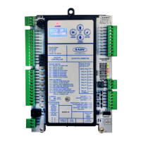
Figure 1: VCCX2 Controller Components ........................................................................................................................... 11
Figure 2: VCCX2 Controller Dimensions ............................................................................................................................. 12
Figure 3: VCC-X EM1 Expansion Module Dimensions ..................................................................................................... 13
Figure 4: 12 Relay E-BUS Module Dimensions .................................................................................................................. 14
Figure 5: VCCX2 Controller Input Wiring ............................................................................................................................. 16
Figure 6: VCCX2 Controller Output Wiring .......................................................................................................................... 17
Figure 7: Entering Water Temperature Sensor, Return Air Plenum Pressure
and Return/Exhaust Proof of Flow ....................................................................................................................... 18
Figure 8: Direct Fire Wiring .................................................................................................................................................... 18
Figure 9: VCC-X EM1 Exhaust Duct Static Pressure and Economizer Actuator Feedback Wiring ........................... 19
Figure 10: VCC-X EM1 Expansion Module Output Wiring .................................................................................................. 20
Figure 11: 12 Relay E-BUS Expansion Module Wiring ....................................................................................................... 21
Figure 12: EBTRON GTC116 or HTN104 Series, GreenTrol GA-200-N Series,
and Paragon MicroTransEQ Series Airow Measurement Digital Transmitter Wiring ................................. 22
Figure 13: Operator Interfaces ................................................................................................................................................ 23
Figure 14: Prism 2 ALARM Button .......................................................................................................................................... 47
Figure 15: Prism 2 ALARM Menu ............................................................................................................................................ 47
Figure 16: Prism 2 Direct Fire Alarms Screen ....................................................................................................................... 49
Figure 17: Prism 2 Compressor Alarms Screen ................................................................................................................... 50
Figure 18: Prism 2 EVAP Module Alarms Screen ................................................................................................................. 50
Figure 19: VCCX2 Controller LED Locations ........................................................................................................................ 58
Figure 20: VCC-X EM1 Expansion Module LED Locations ................................................................................................ 58
Figure 21: Typical Stand-Alone System Layout .................................................................................................................... 62
Figure 22: Typical Networked Single Loop System Layout ................................................................................................ 63
Figure 23: Typical Networked Multiple Loop System Layout .............................................................................................. 64
Figure 24: LCD Display and Navigation Keys ....................................................................................................................... 65
Figure 25: VCCX2 BACnet Connection to MS/TP Network ................................................................................................ 71