TROUBLESHOOTING
MHGRV-X Field Technical Guide
16
Troubleshooting
Other Checks
0-3V (SAT OPTIONS Jumper Settings Normal
And MODGAS-X) & 0-5V (SAT OPTIONS Jump-
er Setting MODGAS) Supply Air Temperature
Sensor
If you suspect the Supply Air Temperature Sensor is not reading
correctly, make sure the wiring terminal connections are tight and
that any wiring splices are properly connected. You can check the
operation of the Supply Air Temperature Sensor by measuring the
resistance or voltage using a digital multimeter. Set the meter to DC
Volts. Place the positive probe on the AIN terminal and the negative
probe on the GND terminal. Read the DC Volts and fi nd that voltage
in Tables 5 & 6.
Read the temperature corresponding with that voltage and determine
if this is close to the actual temperature the sensor is exposed to. If the
temperature from the chart is diff erent by more than a few degrees,
you probably have a defective or damaged sensor. You can also
check the sensor resistance to determine correct operation. To read
the resistance, set the meter to Ohms. Unplug the sensor connector
from the board and measure the resistance across the disconnected
wires. This resistance should match the corresponding temperature
from Tables 5 & 6.
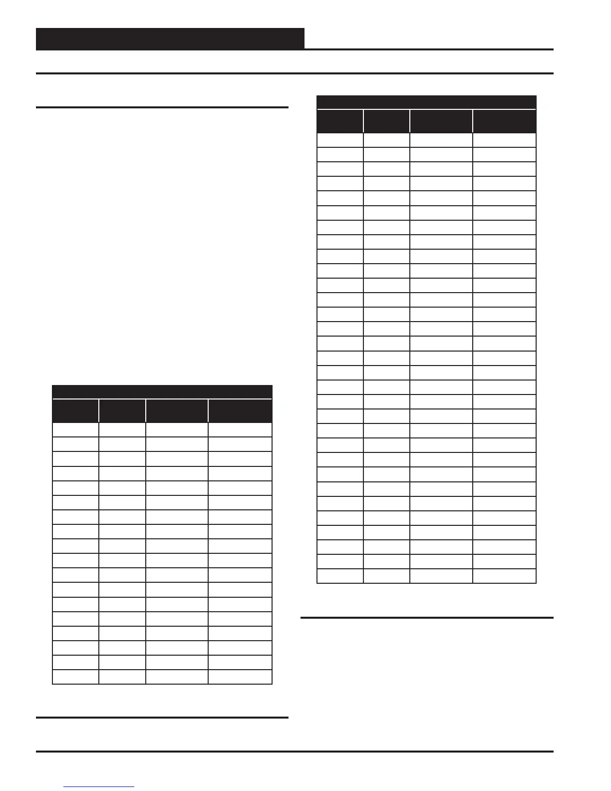
Temperature to Resistance/Voltage Chart
Temp
(°F)
Temp
(°C)
Resistance
(Ohms)
Voltage @
Input (VDC)
-10 -23.3 93333 2.98
-5 -20.6 80531 2.94
0 -17.8 69822 2.89
5 -15.0 60552 2.83
10 -12.2 52500 2.77
15 -9.4 45902 2.71
20 -6.7 40147 2.64
25 -3.9 35165 2.57
30 -1.1 30805 2.49
35 1.6 27140 2.41
40 4.4 23874 2.33
45 7.2 21094 2.24
50 10.0 18655 2.15
52 11.1 17799 2.11
54 12.2 16956 2.08
56 13.3 16164 2.04
58 14.4 15385 2.00
60 15.6 14681 1.96
Temperature to Resistance/Voltage Chart
Temp
(°F)
Temp
(°C)
Resistance
(Ohms)
Voltage @
Input (VDC)
62 16.7 14014 1.93
64 17.8 13382 1.89
66 18.9 12758 1.85
68 20.0 12191 1.81
69 20.6 11906 1.79
70 21.1 11652 1.78
71 21.7 11379 1.76
72 22.2 11136 1.74
73 22.7 10878 1.72
74 23.3 10625 1.70
75 23.9 10398 1.68
76 24.4 10158 1.66
78 25.6 9711 1.63
80 27.8 9302 1.59
82 27.8 8893 1.55
84 28.9 8514 1.52
86 30.0 8153 1.48
88 31.1 7805 1.45
90 32.2 7472 1.41
95 35.0 6716 1.33
100 37.8 6047 1.24
105 40.6 5453 1.16
110 43.3 4923 1.09
115 46.1 4449 1.02
120 48.9 4030 .95
125 51.7 3656 .88
130 54.4 3317 .82
135 57.2 3015 .76
140 60.0 2743 .71
145 62.8 2502 .66
150 65.6 2288 .61
Table 5: 0-3V Temperature Sensor - Voltage &
Resistance for Type III Sensors
Table 5, continued: 0-3V Temperature Sensor -
Voltage & Resistance for Type III Sensors
Thermistor Sensor Testing Instructions
1.) Use the resistance column to check the thermistor sensor while
disconnected from the controllers (not powered).
2.) Use the voltage column to check sensors while connected to
powered controllers. Read voltage with meter set on DC volts. Place
the “-” (minus) lead on GND terminal and the “+” (plus) lead on the
sensor input terminal being investigated.
If the voltage is above 3.3 VDC, the sensor or wiring is “open.” If
the voltage is less than 0.05 VDC, the sensor or wiring is shorted.

 Loading...