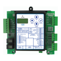
MHGRV-X Field Technical Guide
INPUTS & OUTPUTS
9
Operation Modes
Additional Features
Reheat Coil Flush
To assure positive oil return to the compressor, the Hot Gas Reheat
Coil will be fl ushed of liquid refrigerant by moving the Modulat-
ing Gas Reheat Valve to its maximum position for a short interval.
Cooling Flush: If the unit is in cooling mode, a fl ush will occur
when the unit’s fl ush cooling interval timer has elapsed. The time
is accumulated whenever it is in cooling mode and resets after each
fl ush cycle. The fl ush cooling interval timer is a setpoint that is
confi gurable using the keypad and display (0 to 120 minutes in 10
minute increments).
Reheat Mode Flush: If the unit is in dehumidifi cation mode and
the valve is below 70% for the fl ush reheat interval timer value, a
fl ush will occur. If the valve goes above 70%, the timer is reset. The
fl ush reheat interval timer is a setpoint that is confi gurable using the
keypad and display (0 to 120 minutes in 10 minute increments).
Optional Second Stage Reheat
On larger systems, where more hot gas reheat capacity may be re-
quired, a 2 Position Hot Gas Reheat valve can be connected to the
MHGRV-X Controller to be used in conjunction with the Modulating
Hot Gas Reheat valve. Any time the reheat demand moves above
the Modulating Hot Gas Reheat valve capacity, this 2 position
valve would be energized to supply additional hot gas to the Hot
Gas Reheat coil. As the reheat demand is satisfi ed, the MHGRV-X
Controller will de-energize the 2 position valve and control reheat
with the Modulating Hot Gas Reheat valve.
Reheat Solenoid Valve Control
The Hot Gas Reheat Solenoid valve for the Reheat Coil is activated
when there is a call for Dehumidifi cation. In this mode, the Hot Gas
Reheat Solenoid will be deactivated 2 minutes after the reheat de-
mand ceases. The Hot Gas Reheat Solenoid valve will be reactivated
when a request for reheat is received by the MHGRV-X Controller.
Communicating Operation
In this mode, the MHGRV-X Controller behaves as an expansion
board for an AAON Unit controller. The controller begins the dehu-
midifi cation process when the AAON Unit controller makes a request
to the MHGRV-X Controller for dehumidifi cation. At that time, the
controller will activate the “FAN” output to energize the HVAC unit
fan. At the same time, the controller will initiate Cooling Mode by
energizing the “CMP” output starting the HVAC unit compressor.
In addition, the controller will open the Hot Gas Reheat Coil by
activating the “VALVE” output which opens the Reheat Solenoid
Valve. At this time, the MHGRV-X Controller will start to modulate
the Modulating Hot Gas Reheat valve. The controller will modulate
the MHGR valve to maintain the Supply Air Temperature Setpoint
by activating the stepper motor outputs on the MHGR valve. The
Supply Air Setpoint is set by programming the HVAC unit control-
ler. If Supply Air Temperature Reset is used, it will initiate when
the HVAC sends a request to reset the Supply Air Temperature. The
Supply Air Temperature will be reset towards the Supply Air Reset
Temperature Setpoint stored in the HVAC controller. It will send a
request to move towards the Supply Air Temperature Reset Setpoint
based on its setpoints and confi guration. The controller will conclude
the Dehumidifi cation process when the HVAC control sends a request
to terminate Dehumidifi cation or a Cooling or Heating Override
request is made by the HVAC unit controller. Any setpoints or
signals at the inputs to the MHGRV-X Controller will be ignored.
Auxiliary Mode Communicating
1. Same as the Stand Alone Auxiliary Mode, but the Reheat
Enable and Auxiliary Valve position will be sent using E-BUS
commands.

 Loading...