BDM interface for CodeWarrior™ Debugger, BDI2000 (MPC5xx/8xx) User Manual 4
© Copyright 1992-2001 by ABATRON AG V 1.02
2 Installation
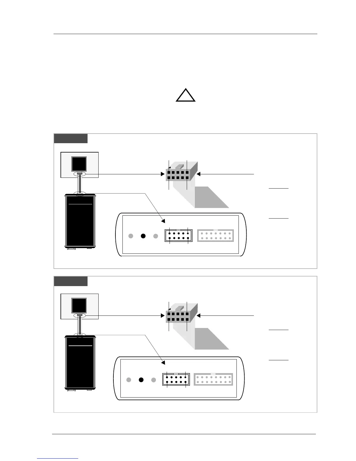
2.1 Connecting the BDI2000 to Target
The cable to the target system is a ten pin flat ribbon cable. In case where the target system has an
appropriate connector, the cable can be directly connected. The pin assignment is in accordance with
the Motorola specification.
In order to ensure reliable operation of the BDI (EMC, runtimes, etc.) the target cable length must not
exceed 20 cm (8").
For BDI MAIN / TARGET A connector signals see table on next page.
!
BDI TRGT MODE BDI MAIN BDI OPTION
Target Connector
BDI2000
AA
AA
bb
bb
aa
aa
tt
tt
rr
rr
oo
oo
nn
nn
AA
AA
GG
GG
SS
SS
ww
ww
ii
ii
ss
ss
ss
ss
MM
MM
aa
aa
dd
dd
ee
ee
Target System
MPC
8xx
9
1
10
2
The green LED «TRGT» marked light up when target is powered up
1 - VFLS0
2 - SRESET
3 - GROUND
4 - DSCK
5 - GROUND
6 - VFLS1
7 - HRESET
8 - DSDI
9 - Vcc Target
10 - DSDO
1
9
2
10
Rev. A
«Rev. A» is the first BDI2000 version, produced until June 1999
Target Connector
BDI2000
AA
AA
bb
bb
aa
aa
tt
tt
rr
rr
oo
oo
nn
nn
AA
AA
GG
GG
SS
SS
ww
ww
ii
ii
ss
ss
ss
ss
MM
MM
aa
aa
dd
dd
ee
ee
Target System
MPC
8xx
The green LED «TRGT» marked light up when target is powered up
1 - VFLS0
2 - SRESET
3 - GROUND
4 - DSCK
5 - GROUND
6 - VFLS1
7 - HRESET
8 - DSDI
9 - Vcc Target
10 - DSDO
1
9
2
10
Rev B/C
BDI TRGT MODE TARGET A TARGET B
9 1
10
2