Operation Manual / A200-L
9 Disassembly and assembly / 9.20 Fitting wall insert
© Copyright 2021 ABB. All rights reserved. HZTL4036_EN Rev.T December 2021
A265-L.. - A280-L..
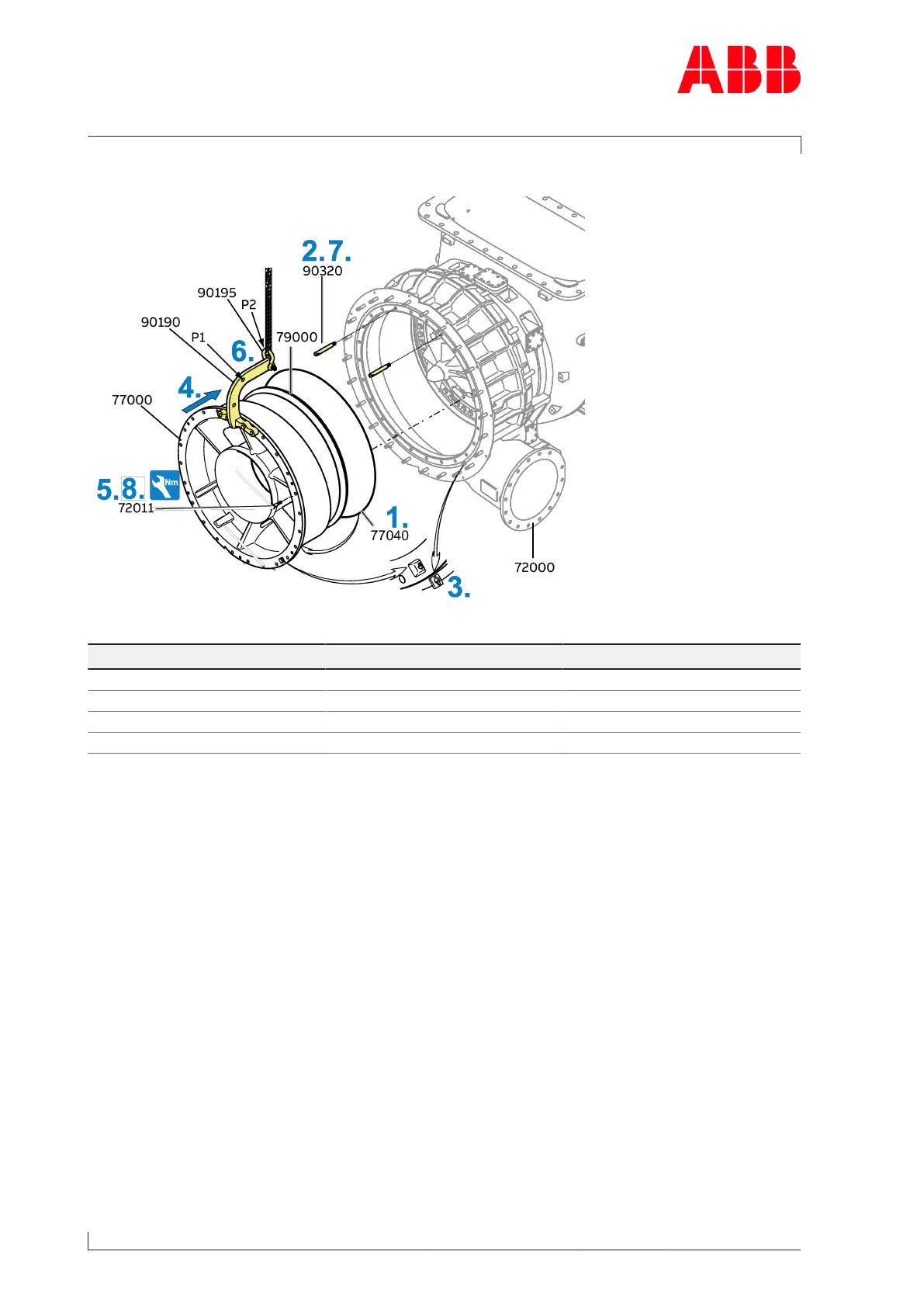
Fig.61: Fitting the wall insert (A265-L.. - A280-L..)
Product Size Tightening torque [Nm]
A265-L M18 370
A270-L M20 500
A275-L M24 900
A280-L M27 1300
Table42: Tightening torque (72011)
1. Attach the new O-ring(77040) to the wall insert(77000).
2. Fit two guide studs(90320) in the upper area of the compressor casing(72000).
3. Align arrow markings of wall insert(77000) and compressor casing to one another.
4. Carefully move the wall insert with diffuser(79000) over the guide studs into the com-
pressor casing. Check the correct position of both casings using the marking arrows.
5. Fit a screw(72011) as a safeguard.
6. Remove the shackle (90195) with lifting gear. Change the position of the shackle with the
lifting gear to P1 of the lifting device (90190) and remove with the crane.
7. Move the wall insert fully in, then remove the guide studs(90320).
8. Fit the screws(72011). Observe tightening torque.
Page 104 / 145