MBP power and line length calculation Section 2 Transmission Technology
36 3BDS009029R5001 B
MBP power and line length calculation
The distribution of stations on the PROFIBUS PA segment can have a negative
effects on the maximum possible line length in certain circumstances. The following
example is intended to clarify this point:
The case in question is an Ex application. The result of the current calculation is that
a maximum direct current including I
FDE
of 100 mA is flowing. Type A cable is
being used with a resistance coating of 44 Ohm/km.
A requirement for a PROFIBUS PA slave to be able to function properly is that the
input voltage on the bus line must be at least 9 V. The following therefore applies to
the maximum voltage drop over the lead:
U
Lmax
= U
out
- 9 V
Currently U
out
for LD 800P with an Ex interface PL 890 is at least 12.8 V (12.8 V ...
13.4). For the worst case consideration, U
out
should be set to 12.8 V. This results in:
U
Lmax
= 12.8 V - 9 V = 3.8 V
Since all stations are connected at the end of the line, the maximum line resistance
must be
R
L
= U
L
/i
max
R
L
= 3.8 V / 100 mA = 38 Ohm
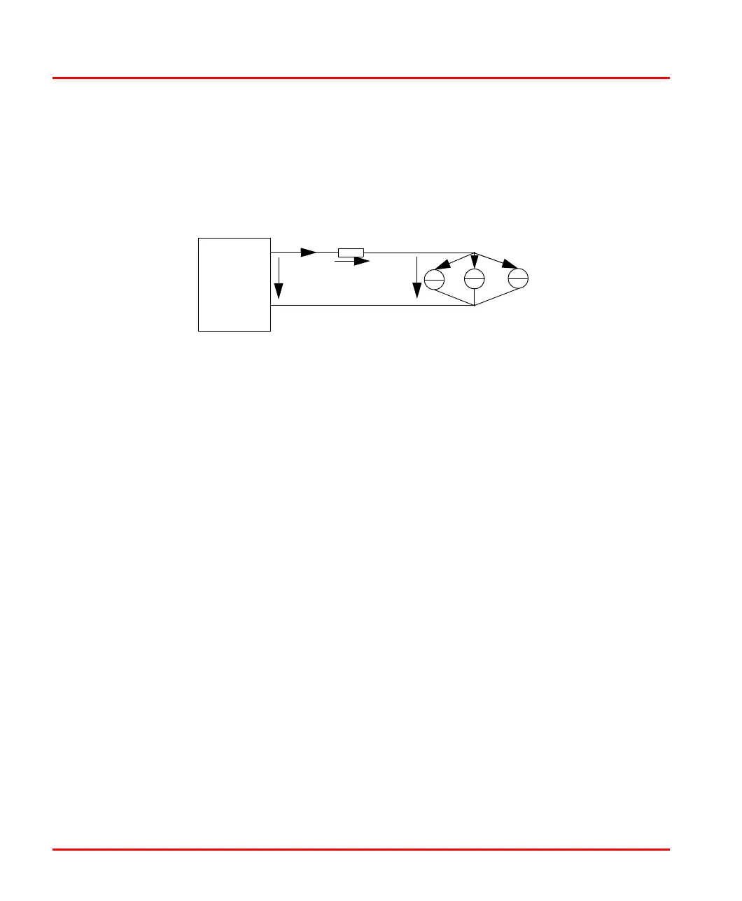
Figure 5. Voltage calculation and line length
Linking
Device/
R
L
R
L
= Line resistance of line segment x
I
x
= Current consumption of PA station x
i
1
i
2
i
n
> 9 V
U
L
U
out
i
max
Power
Link
Module

 Loading...


