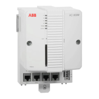
Installation hints for CI854(A) Section 4 Commissioning of PROFIBUS equipment
98 3BDS009029R5001 B
Installation hints for CI854(A)
Use the following procedure to install the CI854(A) (for details see related product
documentation):
1. Install a connector on the shielded twisted pair PROFIBUS DP cable. A
connector with a switchable built-in bus termination is recommended.
Connect the cable screen to the metal case of the connector to ground the
screen via CI854(A). Connect the data cable wire A (green) to the terminal
PIN8 (RxD/TxD-N) and the data cable wire B (red) to the terminal PIN3
(RxD/TxD-P).
2. Connect the cable shield for both lines to functional ground e.g. by using a
grounding clamp.
3. Connect the PROFIBUS DP cable to one of the connectors PROFIBUS A or
PROFIBUS B on the base plate. For support of Line Redundancy connect a
second PROFIBUS DP cable to the other contact.
4. If the CI854(A) is at the end of the PROFIBUS DP cable, switch the bus
termination ON. Otherwise leave the bus termination switched OFF.
5. If the CI854A is installed in a redundant configuration connect the PROFIBUS
DP cable to primary and backup module. Do it like described in Figure 34.
Switch the termination ON for the interface on primary or backup module that
is at the end of the line.

 Loading...


