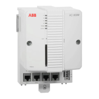
Section 4 Commissioning of PROFIBUS equipment Installing a Redundancy Link Module RLM 01
3BDS009029R5001 B 99
Installing a Redundancy Link Module RLM 01
Use the following procedure to install the RLM 01(for details see related product
documentation):
1. Connect the redundant PROFIBUS lines are connected to ports A and B. Port
M is to be used for the not redundant PROFIBUS line to the master or one of
the slaves. All three PROFIBUS ports, for example A, B and M, have the same
9-pin Sub-D connectors (sockets). The pin assignment is in accordance with
the PROFIBUS standard.
2. If the A/B ports of an RLM 01 module are located at the start or end of a bus
segment, two connector plugs with integrated bus terminating resistors must be
provided. If the M port resides at the start or end of a PROFIBUS, one
connector plug with integrated bus terminating resistors must be provided. It is
preferable to use PROFIBUS terminals with an integrated resistor combination
that can be turned on and off. A short-circuit-proof power supply to supply the
resistors located in the connector is available on pins 5 (VP+) and 6 (DGND).
3. Use only shielded PROFIBUS connectors of suitable design. The connectors
should preferably have a cable connection that is angled down at 35° and is no
wider than 18 mm. The power supply and alarm lines are connected directly to
the terminals labelled 1 to 8.
4. Set the transmission rate with the rotary switch on the front panel before
turning on the power supply. You can select transmission rates of from 9.6
kbit/s to 12 Mbit/s. If the transmission rate is changed during ongoing
operation, you should push the reset button once briefly to reset the control
logic and the counters etc. to a defined initial state.
5. RLM 01 also tests whether the supply voltage is present at inputs L1+ and L2+.
A single power supply with L1+ alone always requires a cable jumper from
L1+ to L2+. This prevents an unwanted error message.

 Loading...


