Section 4 Commissioning of PROFIBUS equipment Testing the PROFIBUS bus cable and bus
3BDS009029R5001 B 105
Testing the PROFIBUS bus cable and bus connectors
The measurements described below allow you to test an installed network and
eliminate the most common errors, such as reversal of the cable polarity, open or
short circuits of data cables or shield and incorrectly connected terminating
resistors. The measurements should be carried out for each bus segment after
installing the PROFIBUS cables and attaching the bus connectors.
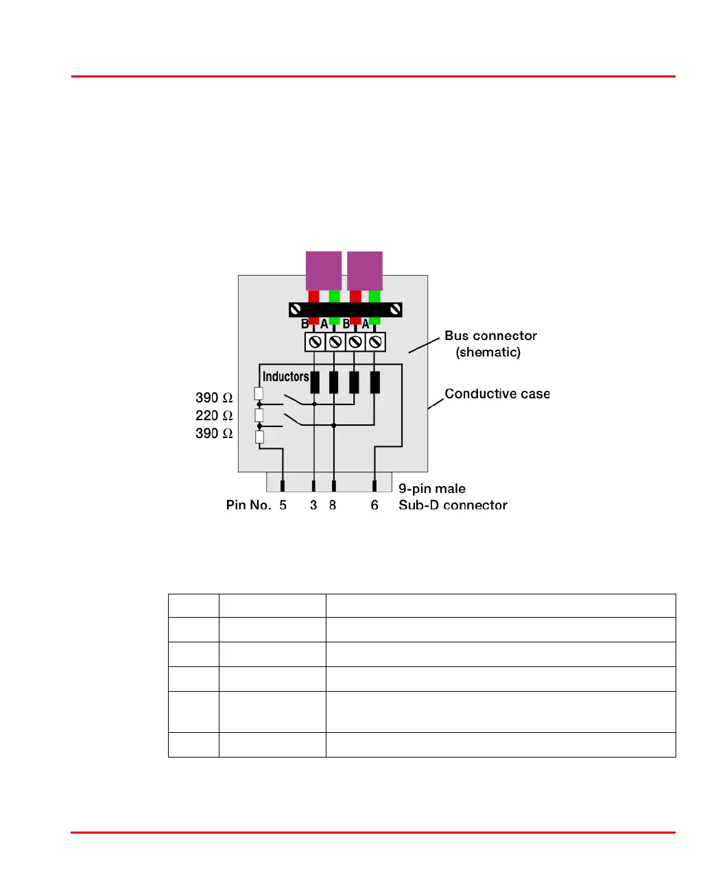
Figure 39. PROFIBUS DP Connector
Table 10. PROFIBUS DP Connector
PIN Designation Description
1 Shield Shield/protective ground
2– Not Used
3 RxD/TxD-P Receive/Transmit Data P-line (B-line, red)
4 CNTR-P repeater control signal,
indicates direction to repeater (TTL)
5 DGND Digital Ground

 Loading...


