Testing the PROFIBUS bus cable and bus connectors Section 4 Commissioning of PROFIBUS
106 3BDS009029R5001 B
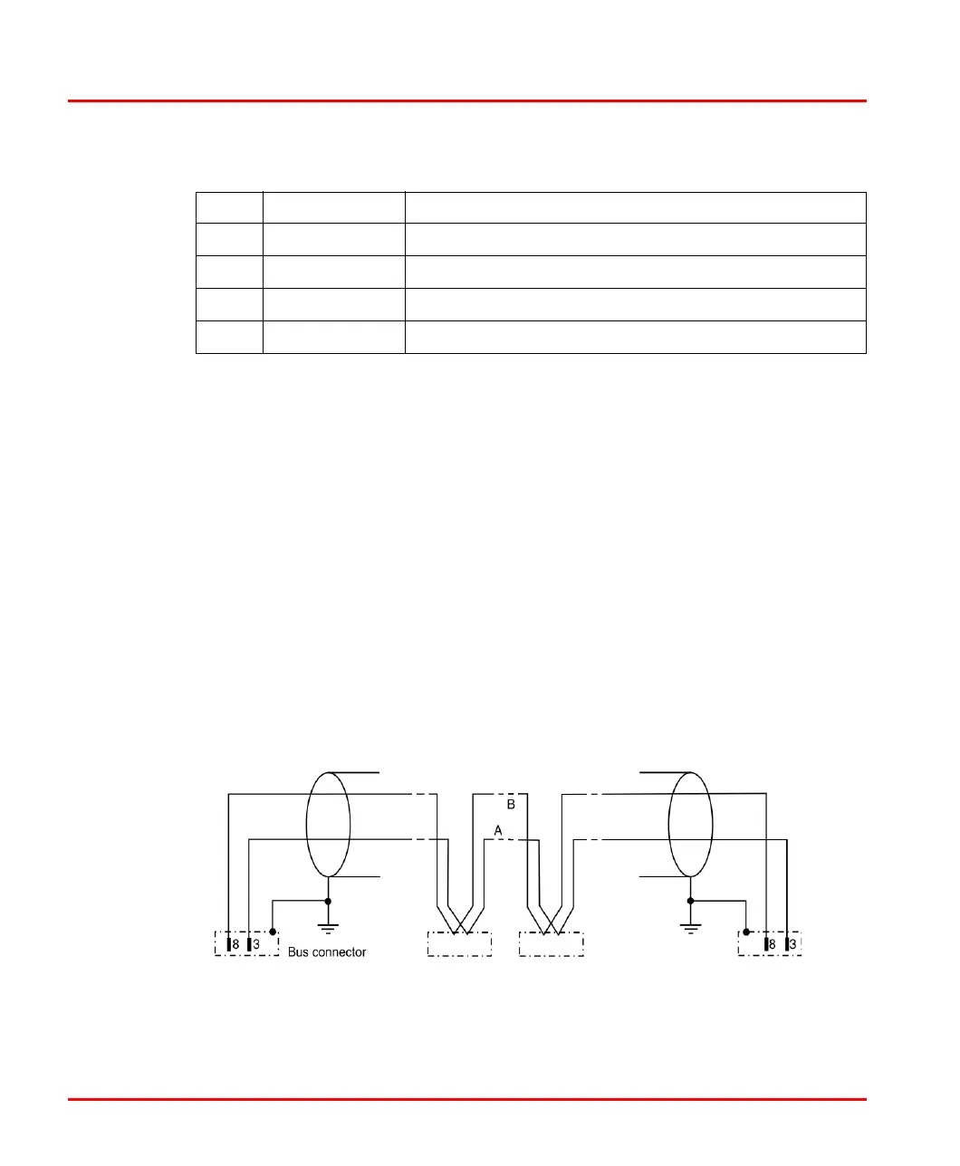
Use an ohmmeter to check the static characteristics of the ready made cable:
• Passage on pin 3 between all PROFIBUS connectors.
• Passage on pin 8 between all PROFIBUS connectors.
• Insulation between pin 3 and pin 8 with bus termination switched off.
• one bus termination switched on é around 390 ohms between pin 3 and 6
• both bus terminations switched on é around 195 ohms between pin 3 and 6
• one bus termination switched on é around 220 ohms between pin 3 and 8.
• both bus terminations switched on é around 110 ohms between pin 3 and 8
• one bus termination switched on é around 390 ohms between pin 8 and 5
• both bus terminations switched on é around 195 ohms between pin 8 and 5
In the values above we have unattended the loop resistance of typical 110 Ohm/km
6 VP +5 V, supply voltage for terminating resistors
7 – Not Used
8 RxD/TxD-N Receive/Transmit Data N-line (A-line, green)
9 DGND Digital Ground
Figure 40. Schematic diagram of testing the PROFIBUS cable
Table 10. PROFIBUS DP Connector
PIN Designation Description

 Loading...


