Section 4 Commissioning of PROFIBUS equipment Testing the PROFIBUS bus cable and bus
3BDS009029R5001 B 107
The following pictures shows the correct installation as well as the common
installation errors. Use an oscilloscope to check the voltage signals on the bus
segment:
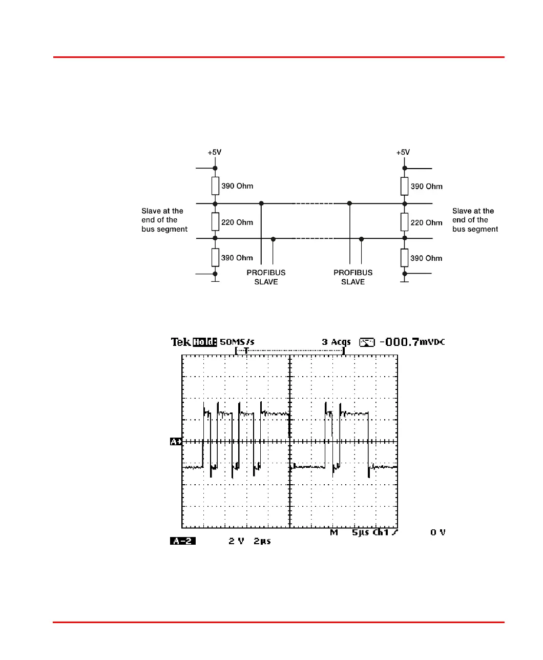
1. A correct PROFIBUS installation:
The measured voltage between the both transmission lines shall be 1,1 V
Figure 41. Correct terminated PROFIBUS line

 Loading...


