Chapter 1 – Introduction
ACS 600 MultiDrive Hardware Manual 1-3
Drive Section
The drive section consists of the parts listed below:
• One to three Drive Units
• Output cubicle (with parallel connected inverter units and units with
motor cable entry and exit through the top of the cabinet)
• DC Fuses or a disconnecting switch (Switch Fuse with Charging
Circuitry)
• Cabinet mechanics
• CDP 31x Control Panel (optional)
• NLMD-01 Monitoring Display (optional).
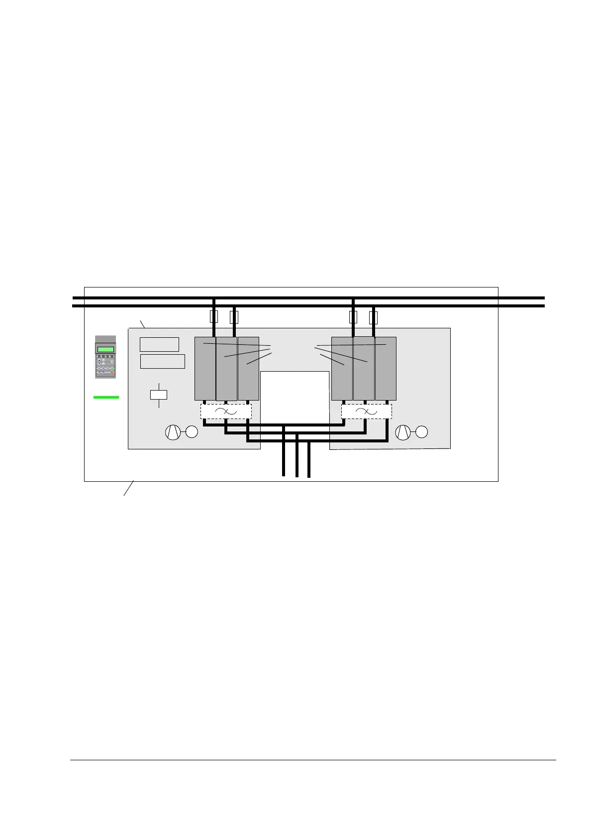
Example A block diagram of a 2 x R11i drive section is shown below.
Drive Unit
The drive unit includes the parts listed below:
• Inverter
• External Inverter Unit Cooling Fans (frames R6i to 4 x R12i only)
• Drive Control Units (NDCU), which include an Application and Motor
Controller (NAMC) Board and a standard I/O (NIOC) Board
• Optical Branching Unit (NPBU) with parallel connected units
• Control wiring and relays (for e.g. optional prevention of unexpected
start)
• du/dt Filters (optional)
Inverter:
Phase
Modules
Drive Unit
NDCU
Motor
+24 VDC
M
I/O options
Output
Cubicle
ACT PAR FUNC DRIVE
ENTER
LOC
REM
RESET REF
%
M
Drive
Section
Optional