ACH550-UH User’s Manual 1-83
Parameters
0116 APPL BLK OUTPUT 0.0…100.0% 0.1% -
(0.0…600.0% for torque)
Application block output signal. Value is from either:
• PFA control, if PFA Control is active, or
• Parameter 0112
EXTERNAL REF 2.
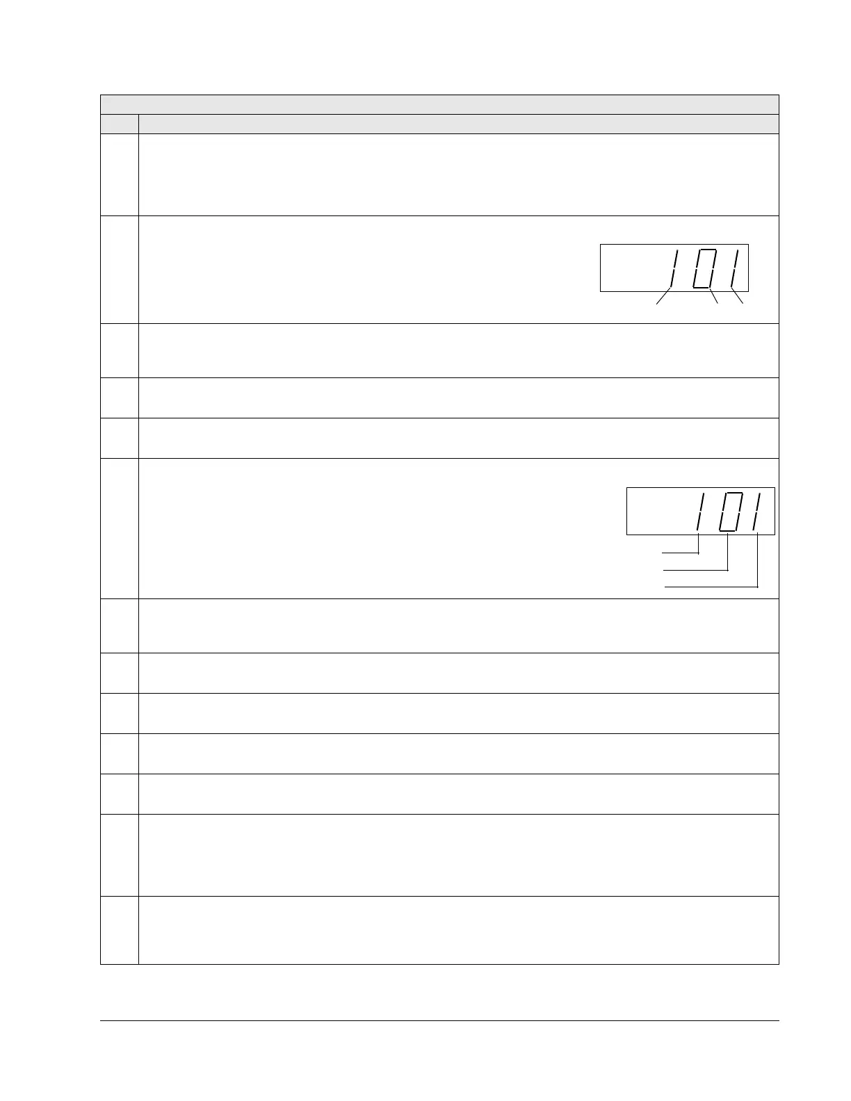
0118 DI 1-3 STATUS 000…111 (0…7 decimal) 1 -
Status of the three digital inputs.
• Status is displayed as a binary number.
• 1 indicates that the input is activated.
• 0 indicates that the input is deactivated.
0119 DI 4-6 STATUS 000…111 (0…7 decimal) 1 -
Status of the three digital inputs.
• See parameter 0118
DI 1-3 STATUS.
0120 AI 1 0.0…100.0% 0.1% -
The relative value of analog input 1 in %.
0121 AI 2 0.0…100.0% 0.1% -
The relative value of analog input 2 in %.
0122 RO 1-3 STATUS 000…111 (0…7 decimal) 1 -
Status of the three relay outputs.
• 1 indicates that the relay is energized.
• 0 indicates that the relay is de-energized.
0123 RO 4-6 STATUS 000…111 (0…7 decimal) 1 -
Status of the three relay outputs. Available if OREL-01 Relay Output Extension Module is installed.
• See parameter 0122.
0124 AO 1 0.0…20.0 mA 0.1 mA -
The analog output 1 value in milliamperes.
0125 AO 2 0.0…20.0 mA 0.1 mA -
The analog output 2 value in milliamperes.
0126 PID 1 OUTPUT -1000.0…1000.0% 0.1% -
The PID controller 1 output value in %.
0127 PID 2 OUTPUT -100.0…100.0% 0.1% -
The PID controller 2 output value in %.
0128 PID 1 SETPNT Unit and scale defined - -
by par. 4006/4106 and
4007/4107
The
PID 1 controller setpoint signal.
• Units and scale defined by PID parameters.
0129 PID 2 SETPNT Unit and scale defined - -
by par. 4206 and 4207
The
PID 2 controller setpoint signal.
• Units and scale defined by PID parameters.
Group 01: Operating Data
Code Description Range Resolution Default S
RELAY 1 STATUS
RELAY
2 STATUS
RELAY
3 STATUS