CHAPTER 9 – CDP CONTROL PANEL 123
9.5 Actual signals mode
Two displays can be selected in the actual signals mode:
• Actual signals display
• Fault memory display
The actual signals display appears first when
entering the actual signals mode. However, when
the drive is in a fault condition, the fault memory
display appears instead.
The actual signals display is used to monitor the
drive without interfering with its operation. It con-
tinuously displays three selectable actual values..
The CDP control panel automatically returns to the
actual signals display from other modes if no key is
actuated within one minute (an exception from
this is the fault memory display).
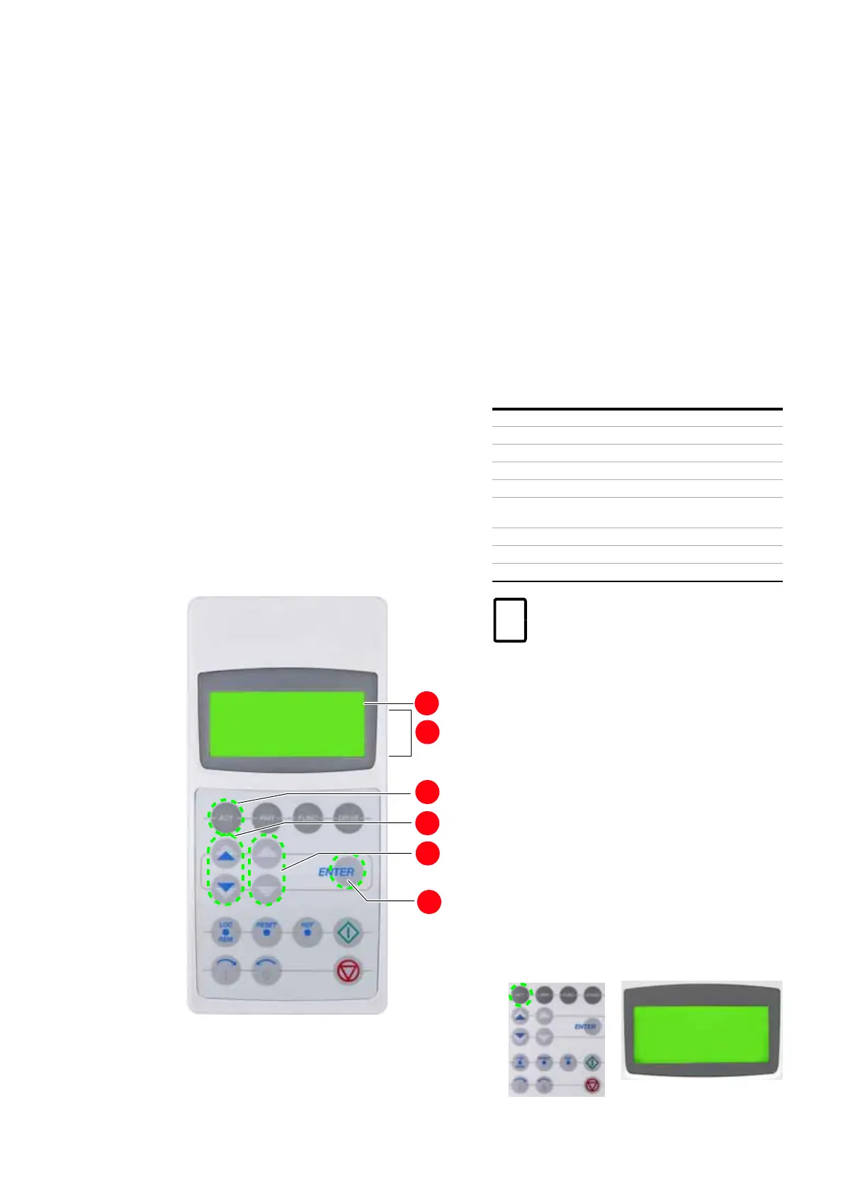
Control panel overview
1. Status line
2. Actual signal names and values
3. Selection key for actual signals mode
4. Fast navigation key for selecting the actual sig-
nals display or the fault memory display
5. Slow navigation key for selecting signals or
fault messages
6. Enter key for confirming the selection
Actual values
The actual values are organized in groups.
Fault memory display
The fault memory display provides information on
the 64 most recent fault events that occurred in
the drive. It displays the name of the fault and the
time it occurred. For instructions on how to display
and reset the fault memory, see 9.5.6 Displaying
and resetting an active fault.
When the drive generates a fault or alarm, the cor-
responding message displays immediately.
Changing from the fault memory mode to other
modes is possible without resetting the fault first.
When no keys is actuated, the fault or warning text
is displayed as long as the fault is active.
9.5.1 Opening the actual signals display
To open the actual signals display, press the ACT
key.
1 L ->
600.0 rpm
StateINU
ReadyOn
MOTOR SP 0.00 rpm
POWER
0.0 kW
1
2
3
4
5
6
Group 01 Measured or calculated motor values
Group 02 Measured or calculated drive values
Group 03 Reference values
Group 04 I/O status signals
Group 05 Communication link andMCB status signals
Group 06 Software version, drive and motor nominal
values
Group 07 Control words
Group 08 Status words
Group 09 Fault and alarm words
For
the complete list of selectable actual
signals, see signal and parameter table
.
1 L ->
600.0 rpm
StateINU
ReadyOn
MOTOR SP 0.00 rpm
POWER
0.0 kW