CHAPTER 2 – POWER ELECTRONICS AND CABINET FEATURES 41
2.6.2 Function
Fan groups
For control reasons, the fan unit(s) of the drive and
the integrated transformer are combined to
groups.
• Fan unit 1 of the drive and fan unit 1 of the inte-
grated transformer belong to group 1.
• Fan unit 2 of the drive and fan unit 2 of the inte-
grated transformer belong to group 2.
• Fan unit 3 of the drive and fan unit 3 of the inte-
grated transformer belong to group 3.
The fan units of a group are always switched on
and off together.
Starting, stopping
The standard fan unit or fan group 1 is switched on
by the control system of the drive when the
charging of the DC link is initiated. When the drive
is stopped, the fan units continue to run for a pre-
set time after the main power has been switched
off and the DC link voltage has decreased below a
preset value.
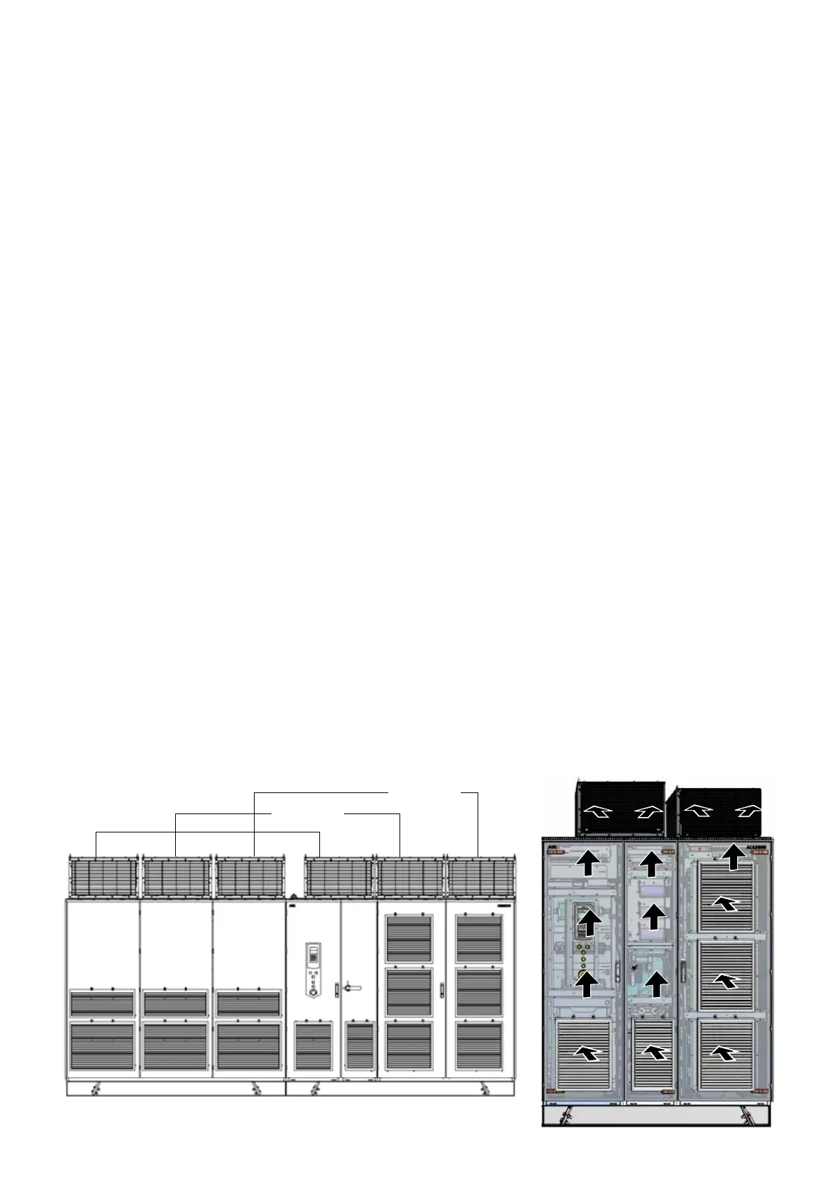
Air flow inside the drive
The fan unit feeds the cooling air to the main
power electronic components and transfers the
heat to the outside of the cabinet.
The air enters the drive cabinet through the lou-
vered panels at the front, passes the phase mod-
ules in the DFE-INU compartment and the EMC
filter and exists through the fan outlet at the front.
2-15 Example of fan unit
groups
2-16 Air flow through the
drive
ACS2000 DFE 4MVA - redundant fan configuration
Fan group 3
Fan group 1
Fan group 2