12 EN – R6…R9 Quick installation guide
For information on reforming the capacitors, see Converter module capacitor
reforming instructions (3BFE64059629 [English]), available on the Internet at
www.abb.com/drives/documents
.
Select the power cables
Size the power cables according to local regulations to carry the nominal current
given on the type designation label of your drive.
Ensure the cooling
See table IEC ratings at UN = 230 V, 400 V and 480 V on page 7 for the losses. The
allowed operating temperature range of the drive is -15 to +50 °C (+5 to +122 °F). No
condensation or frost is allowed. For more information on the ambient temperature
and derating, see chapter Technical data in ACS580-01 (0.75 to 250 kW, 1.0 to
350 hp) hardware manual (3AXD50000044794 [English]).
Protect the drive and input power cable
See tables gG fuses (on page 8) and uR or aR fuses (on page 9) for the fuses.
If you use gG fuses, make sure that the operating time of the fuse is below
0.5 seconds. Follow the local regulations.
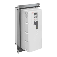
Install the drive on the wall
Warning! The drive module is heavy (42 to 103 kg / 93 to 227 lb). Use a
suitable lifting device. Do not lift the module manually. Make sure that the wall
and the fixing devices can carry the weight.
Install the drive on the wall
See figure R6…R9 Figures A on page 31.
Check the insulation of the power cables and the motor
Check the insulation of the input cable according to local regulations before connecting
it to the drive.
See figure B on page 31.
1. Check the insulation of the motor cable and motor when the cable is disconnected
from the drive. Measure the insulation resistance between each phase conductor
and then between each phase conductor and the Protective Earth conductor
using a measuring voltage of 1000 V DC. The insulation resistance of an ABB

 Loading...