114 The internal cooling circuit
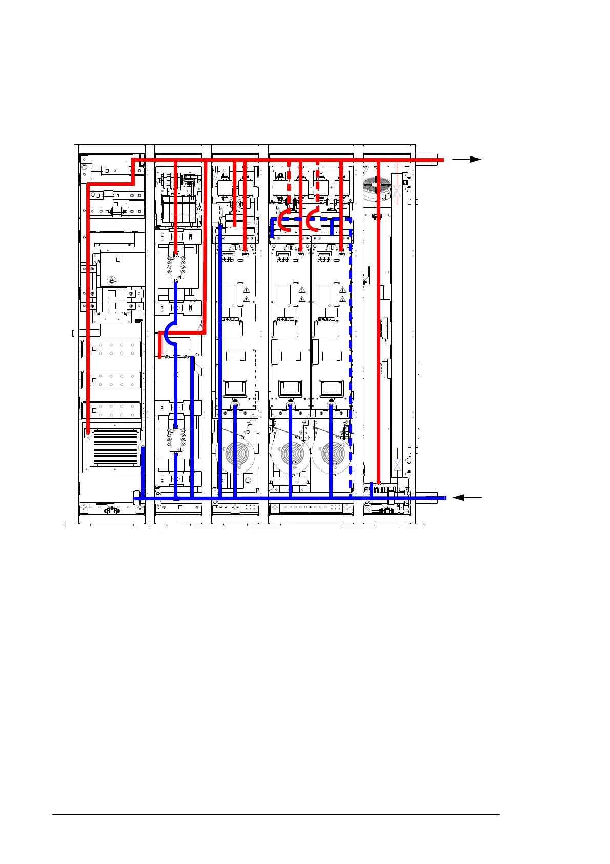
Diagram of the internal cooling circuit
The following diagram shows how the coolant circulates in the converter system.
The power modules in each cubicle can not be isolated from the main cooling circuit. The
converter is equipped with a drain valve and a bleed valve.
Planning the cooling system
Connection to a customer cooling unit
General requirements
Equip the system with an expansion tank to damp pressure rise due to volume changes
when the temperature varies. Keep the pressure within the limits specified in
Specifications below. Install a pressure regulator to ensure that the maximum permissible
operating pressure is not exceeded.
Install a bleed valve at the highest point of the cooling circuit. Install a drain valve below
the lowest pipe in the cooling circuit.
The materials used in the cooling system are listed in Specifications on page 117.

 Loading...


