68 Electrical installation
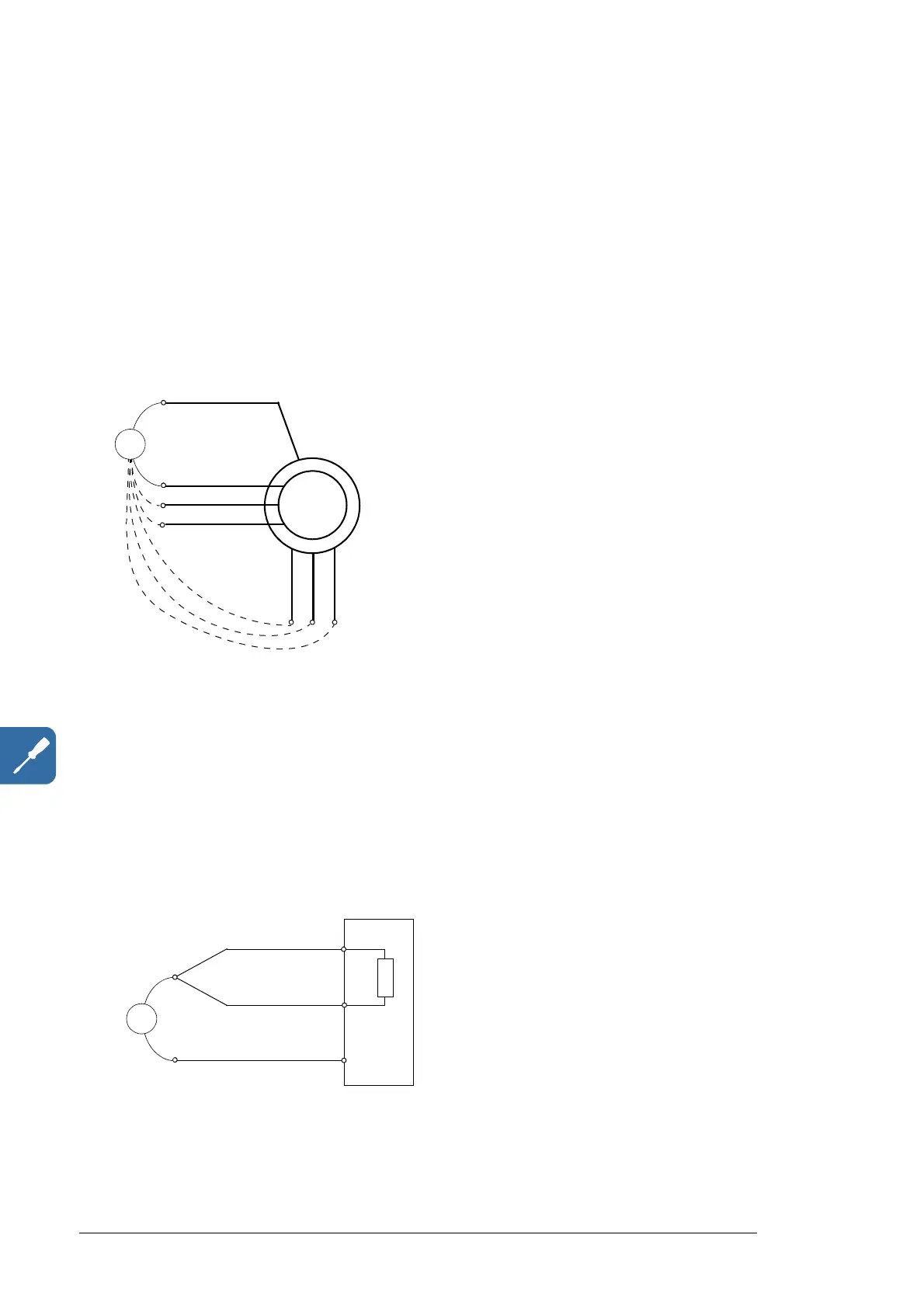
Rotor and rotor cable
1. Check that the generator rotor cable is connected to the generator (terminals K, L and
M), and the stator cable is connected to the generator (terminals U, V and W).
2. Ensure that the other ends of the cables are unconnected.
3. Measure the insulation resistance between each phase conductor and the protective
earth conductor using a measuring voltage of 1 kV DC. Measure both rotor and stator
cables. The insulation resistance of an ABB generator must exceed 100 Mohm
(reference value at 25 °C (77 °F)). For the insulation resistance of other generators,
please consult the manufacturer’s instructions. Note: Moisture inside the generator
casing will reduce the insulation resistance. If moisture is suspected, dry the generator
and repeat the measurement.
DC resistor and resistor cable
Option +D150
• Check that the resistor cable is connected to the resistor and disconnected from the
converter output terminals R+ and R-. At the converter end, connect the R+ and R-
conductors of the resistor cable together.
• Measure the insulation resistance between the combined conductors and the PE
conductor by using a measuring voltage of 1 kV DC. The insulation resistance must be
higher than 1 Mohm.
Option +D150+D151
Every converter equipped with integrated DC resistor is tested for insulation between the
main circuit and the chassis at the factory (2700 V rms 50 Hz for 1 second). Do not make
any voltage tolerance or insulation resistance tests.

 Loading...


