Selecting the power cables
ACS880-304LC +A019 diode supply modules: Obey the power cable selection instructions
in ACS880-304LC+A019 diode supply modules hardware manual (3AXD50000045157
(English)).
■ General guidelines
Select the input power and motor cables according to local regulations.
• Current: Select a cable capable of carrying the drive (or motor) nominal current.
• Temperature: For IEC, select a cable rated for at least 70 °C (90 °C for IP55 [UL Type
12]) maximum permissible temperature of conductor in continuous use. For North
America, power cables must be rated for 90 °C (194 °F) or higher with derating.
• Voltage: 600 V AC cable is accepted for up to 500 V AC. 750 V AC cable is accepted
for up to 600 V AC. 1000 V AC cable is accepted for up to 690 V AC.
Use symmetrical shielded power cables. They reduce electromagnetic emissions of the
whole drive system as well as the stress on motor insulation, bearing currents and wear.
To comply with the European EMC requirements, use a preferred cable type. See
Recommended power cable types (page 24).
If the cabling is in a metal conduit, it reduces the electromagnetic emission of the whole
drive system.
The protective conductor must always have an adequate conductivity. Unless local wiring
regulations state otherwise, the cross-sectional area of the protective conductor must agree
with the conditions that require automatic disconnection of the supply required in 411.3.2.
of IEC 60364-4-41:2005 and be capable of withstanding the prospective fault current during
the disconnection time of the protective device. The cross-sectional area of the protective
conductor can either be selected from the table below or calculated according to 543.1 of
IEC 60364-5-54.
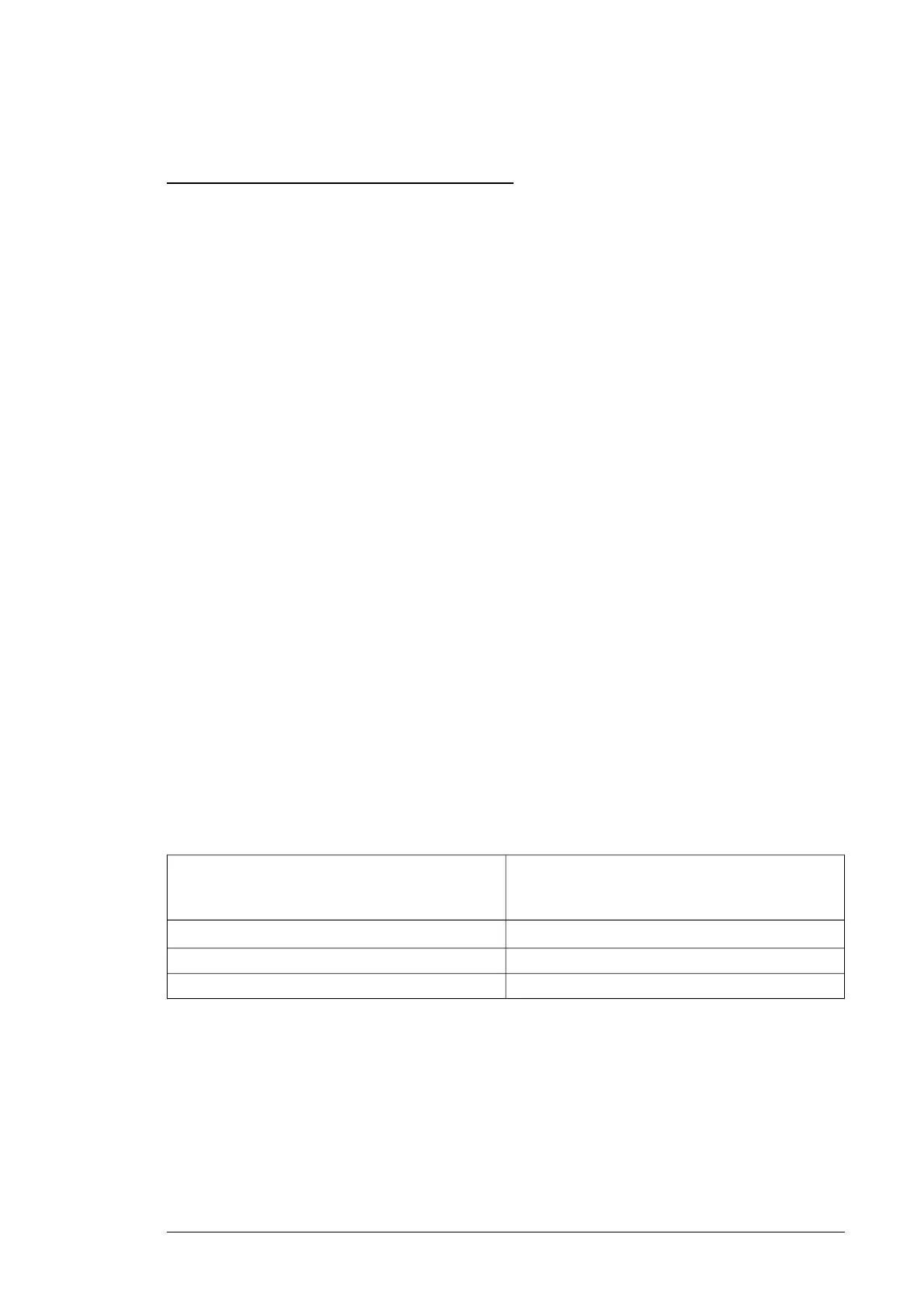
This table shows the minimum cross-sectional area of the protective conductor related to
the phase conductor size according to IEC 61800-5-1 when the phase conductor and the
protective conductor are made of the same metal. If this is not so, the cross-sectional area
of the protective earthing conductor shall be determined in a manner which produces a
conductance equivalent to that which results from the application of this table.
Minimum cross-sectional area of the corresponding
protective conductor
S
p
(mm
2
)
Cross-sectional area of the phase conductors
S (mm
2
)
S
1)
,
2)
S ≤ 16
1616 < S ≤ 35
S/235 < S
1)
Drive safety standard IEC/EN 61800-5-1:
• use a protective earth conductor with a cross-section of at least 10 mm
2
(8 AWG) Cu or 16 mm
2
(6 AWG) Al, or
• use a second protective earth conductor of the same cross-sectional area as the original protective earthing conductor,
or
• use a device which automatically disconnects the supply if the protective earth conductor breaks.
2)
Drive safety standard IEC/EN 61800-5-1: If the protective earth conductor is separate (ie, it does not form part of the input
power cable or the input power cable enclosure), the cross section must be at least:
• 2.5 mm
2
(14 AWG) when the conductor is mechanically protected, or
• 4 mm
2
(12 AWG) when the conductor is not mechanically protected.
■ Typical power cable sizes
See the technical data of the drive (or unit).
Electrical planning guidelines 23

 Loading...


