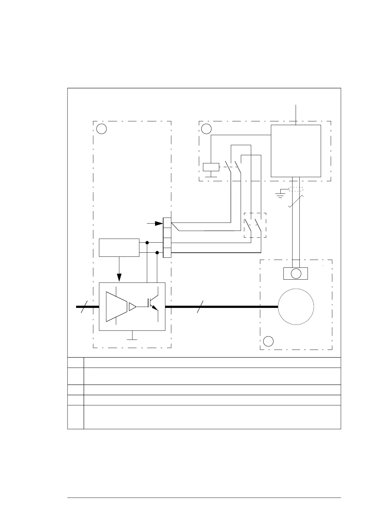
■ Connection diagram
The diagram below shows the connections. The system integrator must get the components
and do the installations drawn outside the drive border line.
3
3
~
Ex M
24 … 240 V AC / DC
3
4
+24 V
XSTO
1
2
3
4
1 2
a)
4
3
Drive1
ATEX-compliant protection relay. The relay monitors a sensor circuit, and activates the STO function of
the drive by opening the control circuits when necessary.
2
Motor temperature sensor3
Potentially explosive atmosphere4
You can use the drive STO function for several external safety functions at the same time (for example,
ATEX-compliant motor thermal protection and emergency stop). If you do, you must connect the STO
activation switches or relays used in other safety functions in series with the protection relay.
a)
Implementing a motor thermal protection circuit 17

 Loading...


