Make sure that at least one of these indications generates a fault if:
• the protection relay does not contain a manual reset, and
• the FSO module is not configured for an STO manual reset.
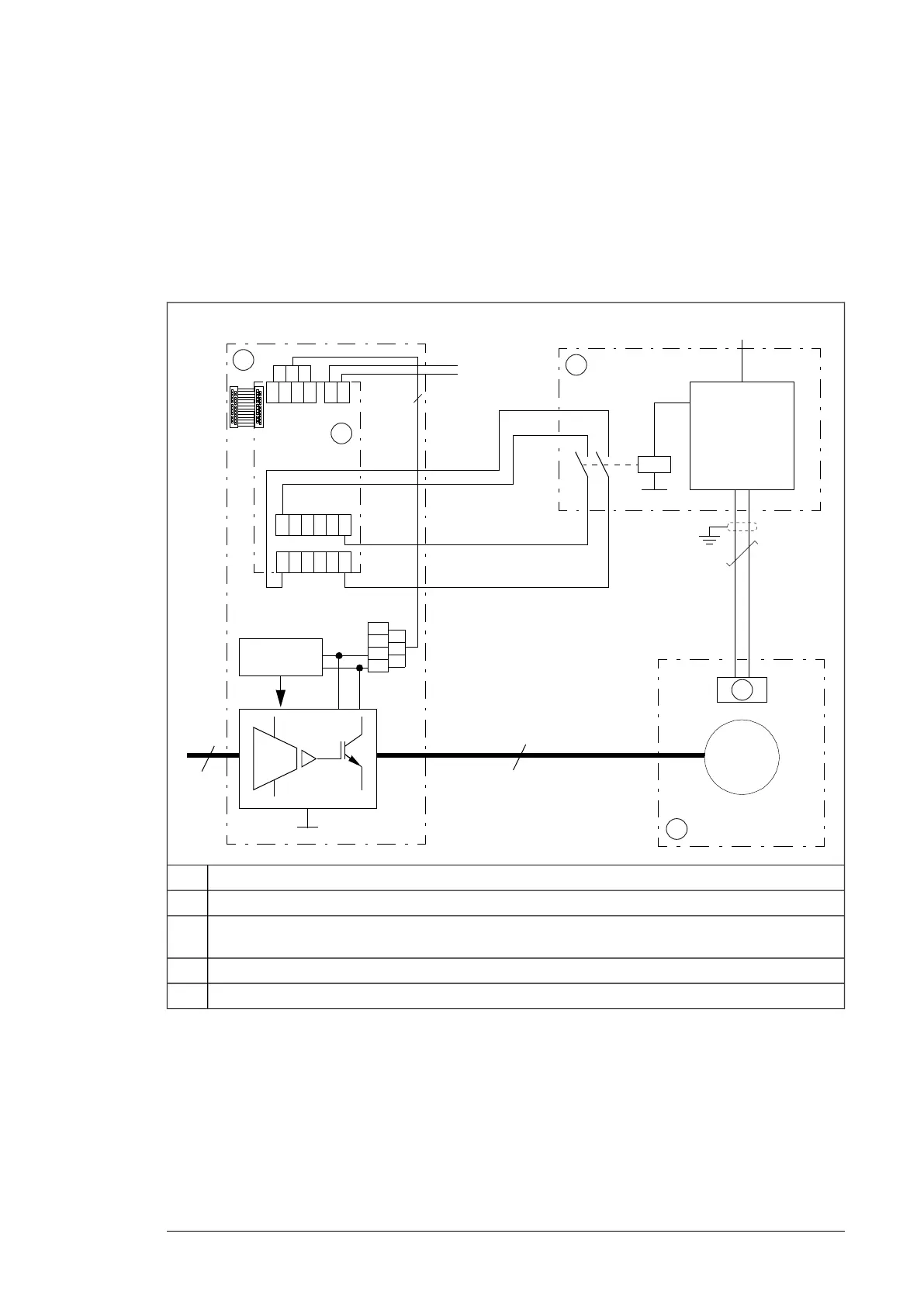
■ Connection diagram (two-channel connection)
The diagram below shows the wiring of the two-channel connection. The system integrator
must get the components and do the installations drawn outside the drive border line.
3
24 … 240 V AC / DC
XSTO
1
2
3
4
1 2 3 4 1 2
24 V / 1 A
X111 X112
X110
X112
1 2 3 4 …10
1 2 3 4 …10
X113
X114
1
2
3
4
3
~
Ex M
5
Drive1
FSO module2
ATEX-compliant protection relay. The relay monitors a sensor circuit, and de-energizes the FSO module
input by opening the control circuits when necessary.
3
Motor temperature sensor4
Potentially explosive atmosphere5
Implementing a motor thermal protection circuit 21

 Loading...


