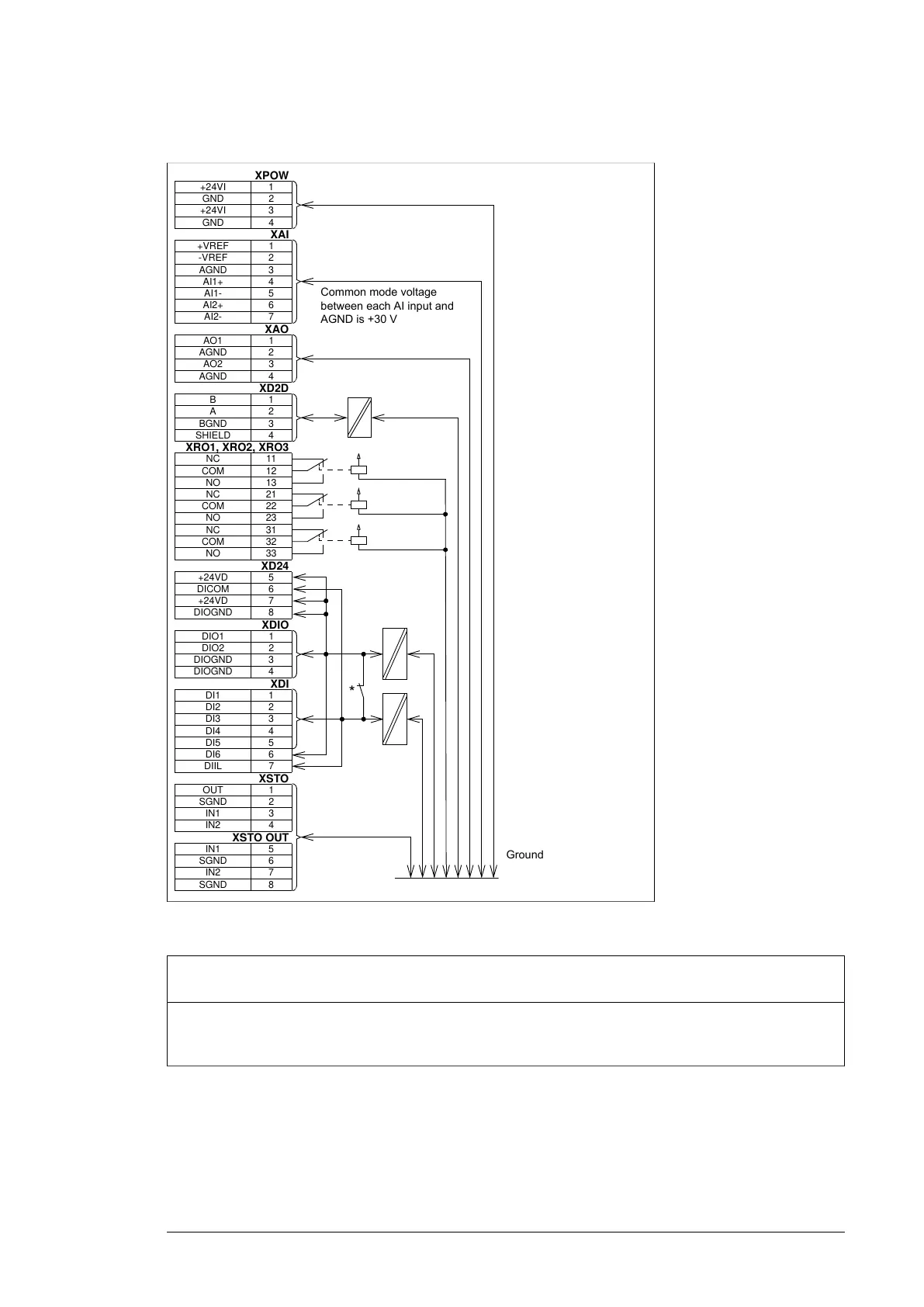
■ BCU-x2 ground isolation diagram
Control units of the drive 137
Ground isolation diagram
XPOW
+24VI 1
GND 2
+24VI 3
GND 4
XAI
+VREF 1
-VREF 2
AGND 3
AI1+ 4
AI1- 5
AI2+ 6
AI2- 7
XAO
AO1 1
AGND 2
AO2 3
AGND 4
XD2D
B1
A2
BGND 3
SHIELD 4
XRO1, XRO2, XRO3
NC 11
COM 12
NO 13
NC 21
COM 22
NO 23
NC 31
COM 32
NO 33
XD24
+24VD 5
DICOM 6
+24VD 7
DIOGND 8
XDIO
DIO1 1
DIO2 2
DIOGND 3
DIOGND 4
XDI
DI1 1
DI2 2
DI3 3
DI4 4
DI5 5
DI6 6
DIIL 7
XSTO
OUT 1
SGND 2
IN1 3
IN2 4
XSTO OUT
IN1 5
SGND 6
IN2 7
SGND 8
*
Common mode voltage
between each AI input and
AGND is +30 V
Ground
*Ground selector (DICOM=DIOGND) settings
DICOM=DIOGND: ON
All digital inputs share a common ground (DICOM connected to DIOGND). This is the default setting.
DICOM=DIOGND: OFF
Ground of digital inputs DI1…DI5 and DIIL (DICOM) is isolated from DIO signal ground (DIOGND). Isolation
voltage 50 V.
Control units of the drive 205

 Loading...