10
Configuration steps
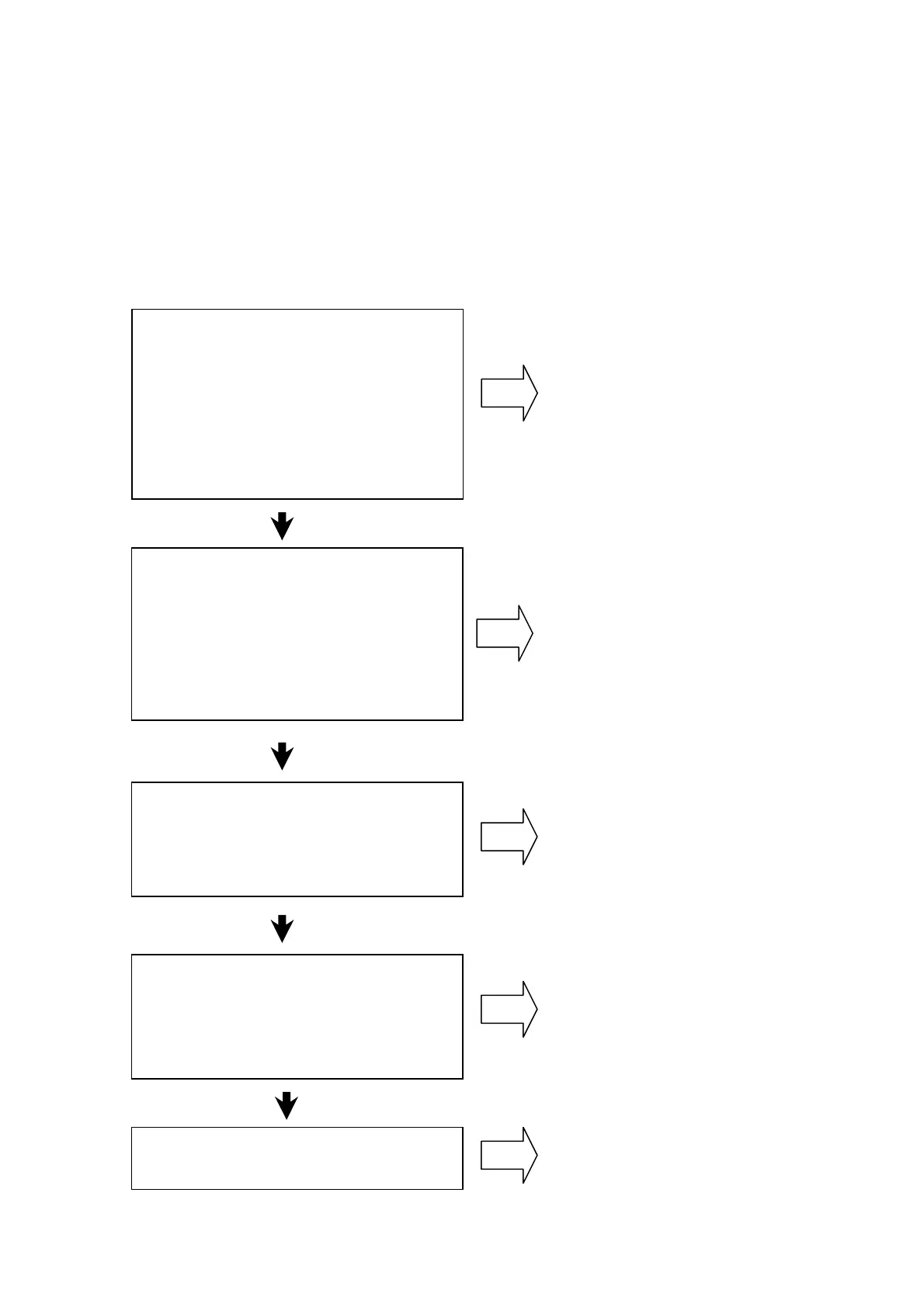
Here is a simple flowchart for configuring a common DC system. Each
configuration step is described in more detail in the related paragraphs.
Configuration step
Related paragraph
Define the common DC power profile
• DC link power versus time for
each axis
• Average and maximum total
motoring power
• Average and maximum total
regenerative power
Select the drive module(s) to be
connected to the AC supply
• Single AC input
• Multiple AC input
• Charging capacity
Select the mains choke(s)
• AC input current
• Harmonic distortion (THD)
See “Power requirements”
See “Supply unit selection”
See “Mains choke selection”
Regenerative power handling
• Energy capacity in the DC link
• Resistor braking
See “Regenerative power”
General system design (fuses, EMC,
installation,…)
See “General system design items”

 Loading...


